
“FemTech Op-lyser om historien om Rosalind Franklin”
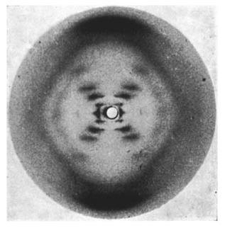
At the year’s first FemTech workshop, we focus on the discovery of DNA’s double helix structure. We will delve into the story of how, by sending X-rays through a DNA molecule, Franklin was able to determine its appearance from the pattern it created. The famous Photo 51:
Through our own experiments – inspired by Franklin’s pioneering work – we must use this insight to build a bridge between a creative, physical expression and then a digital output.
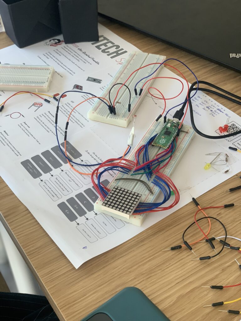
We work with simple microcontrollers and light sensors, and as a participant at Femtech you gain the prerequisites to code for tangible applications of the technology. Making our photographs:
The vision is as always: through inspiring co-creation and practical knowledge of interactive technologies, we must see what it takes to realize wild and innovative ideas when working with concrete development as well as appropriate and engaging design.
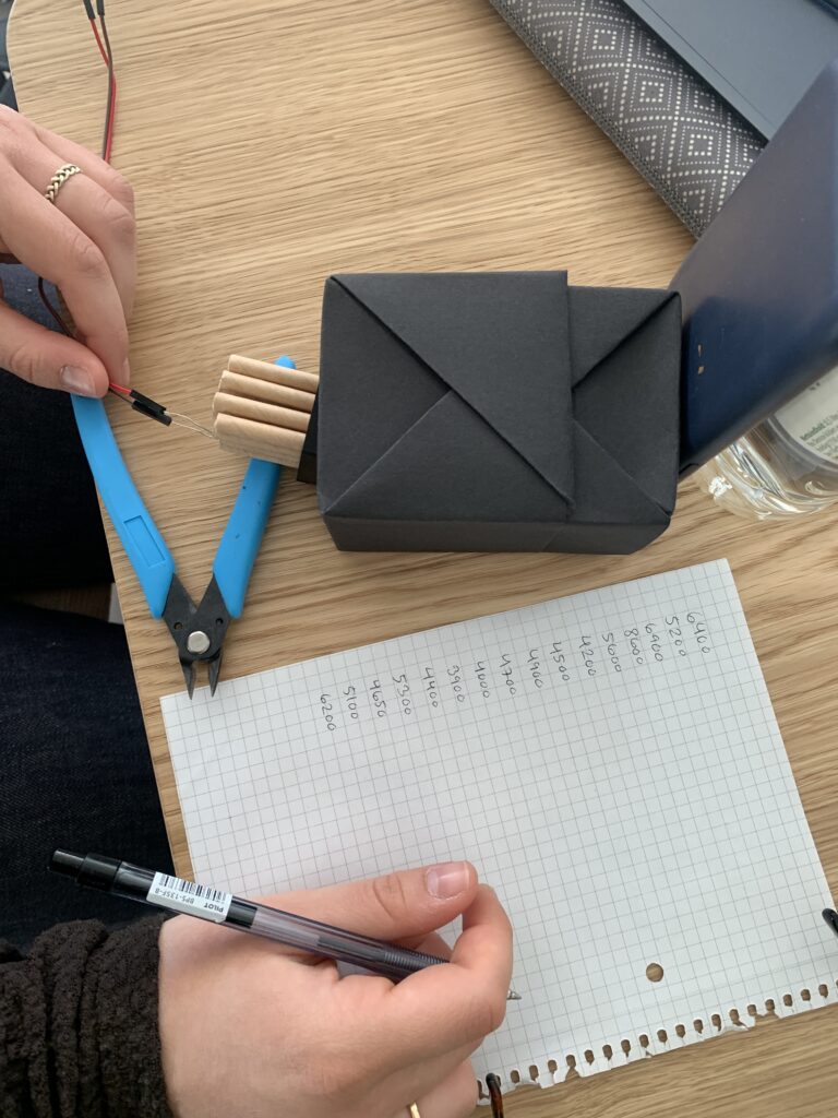
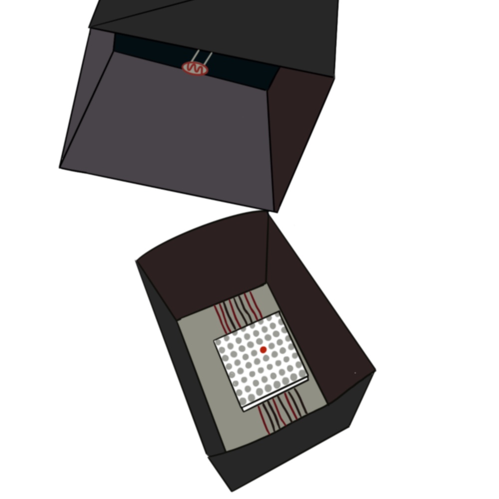
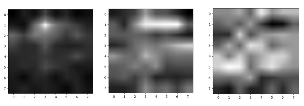
The goal is to simplify and understand the way that an x-ray photo is taken, to make our own micro camera. By using a photoresistor and a LED matrix into a black box (also referring to the fact that some things about cameras is like a black box that we do not understand), and by lighting up the led matrix, with different things blocking the light, so the photoresistor is measuring the values. Lighting up one led, on the led matrix, at a time, the photoresistor measured one value each time a led lighted up, ending up with and string of 64 values.
Led we used Jupiter notebook, to paste the values, like the matrix, so we got an output like a picture of what we blocked in the light in the black box.
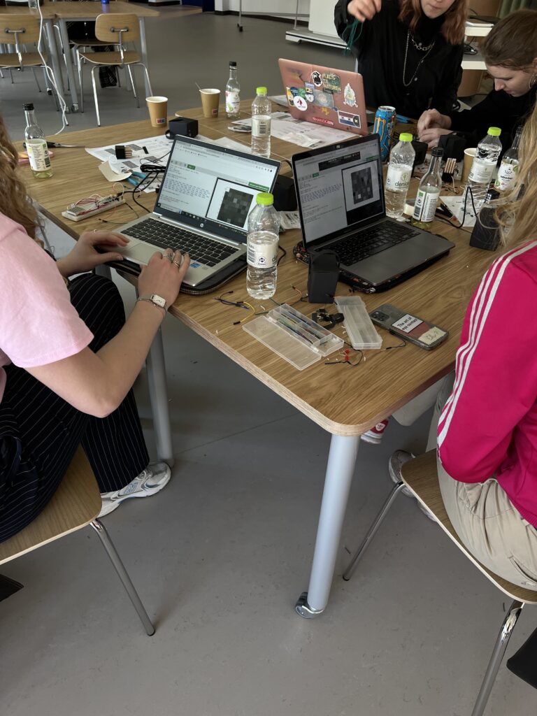
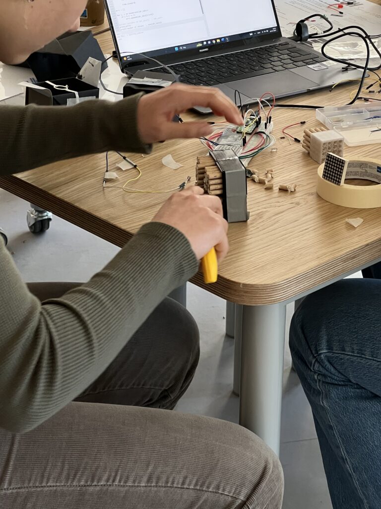
On the tables we had prepared all the small devices that the students needed for the project. They were presented on a paper, where the students could also find the timetable, a cheat sheet on some of the simple code, as well as an overview of the devices they needed to use.
You need:
- Computer using the Thonny Editor
- Raspberry Pi Pico
- Led Matrix (number)
- Photoresistor
- Jumperwires
- Breadboard
- Black cardboard
Step 1 – The power
The initial exercises learning the power of the RaspPi
For the first circuit you need:
- Led (Long leg connects to power, short leg to GND)
- Resistor (placed before the power in the circuit)
- Raspberry PI Pico, using 3V3(power) and GND
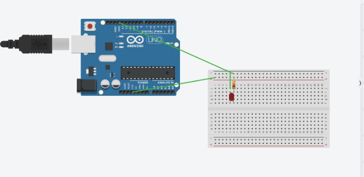
OBS: on the picture we are using an Arduino, when using a Raspberry PI Pico, the pinmap is different, see the pinmap for Raspberry Pi Pico below.
For the second circuit you need:
- Led (Long leg connects to power, short leg to GND)
- Photoresistor (replacing the resistor you had before)
- Raspberry PI Pico, using 3V3(power) and GND
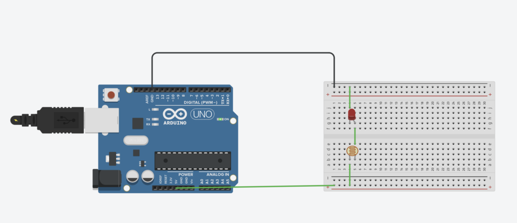
Try to put your finger on the photoresistor and see how the LED reacts.
Try using the light on our phone to light on the photoresistor and see how the LED reacts.
When the led is controlled by how much/little light you give the photoresistor, the first step is done.
Step 2 – The code
Now we need to make two circuits and instead of using the power output, we will use a pin on the Raspberry Pi pico where we can use the input from the photoresistor and use it for the led as an output. The goal is that the photoresistor input, controls the light on the led.
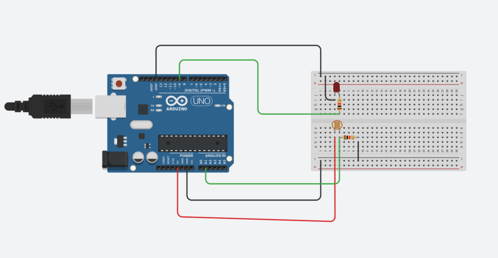
OBS: remember that the picture is using an Arduino, find the Raspberry Pi pico pinmap in the step above.
When we are using the photoresistor we need to use an ADC pin.
Read more about what it means to use an ADC pin in the powerpoints below:
The code for the circuit:
from machine import ADC, Pin
import time

# brug photoresistor som input ...
# først definerer vi den pågældende pin (her pin 26)
ldr = machine.ADC(26)

#brug LED som output (her pin 27)
pin = Pin(27, mode=Pin.OUT)


#denne kode gør at vi får en LDR (photoresistor) værdi i konsollen
#samtidig lader vi LED'en blinke i et tidsinterval
for i in range(100):

    # spørg efter LDR-værdien
    ldr_value = ldr.read_u16()
    print(ldr_value)

    pin.value(1)
    time.sleep (0.5)
    pin.value(0)
    time.sleep (0.5)
Step 3 – The matrix
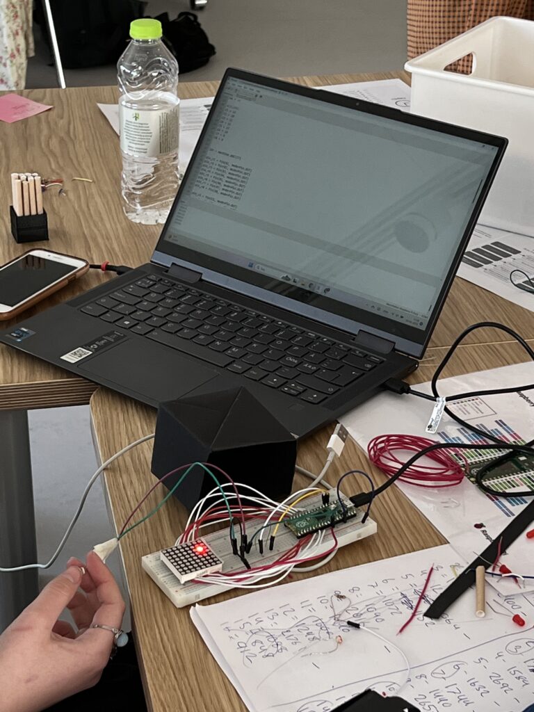
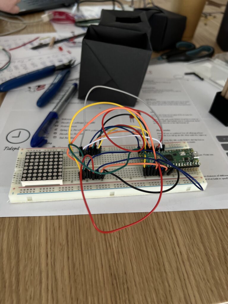
What the setup should look like when testing the matrix:
Code for using the matrix:
from machine import ADC, Pin
import time

# ROWS
R1 = 18
R2 = 17
R3 = 19
R4 = 16
R5 = 14
R6 = 26
R7 = 15
R8 = 13

#COLUMNS
C1 = 12
C2 = 20
C3 = 21
C4 = 11
C5 = 22
C6 = 10
C7 = 9
C8 = 8


ldr = machine.ADC(27)

pin_r1 = Pin(R1, mode=Pin.OUT)
pin_r2 = Pin(R2, mode=Pin.OUT)
pin_r3 = Pin(R3, mode=Pin.OUT)
pin_r4 = Pin(R4, mode=Pin.OUT)
pin_r5 = Pin(R5, mode=Pin.OUT)
pin_r6 = Pin(R6, mode=Pin.OUT)
pin_r7 = Pin(R7, mode=Pin.OUT)
pin_r8 = Pin(R8, mode=Pin.OUT)

pin_c1 = Pin(C1, mode=Pin.OUT)
pin_c2 = Pin(C2, mode=Pin.OUT)
pin_c3 = Pin(C3, mode=Pin.OUT)
pin_c4 = Pin(C4, mode=Pin.OUT)
pin_c5 = Pin(C5, mode=Pin.OUT)
pin_c6 = Pin(C6, mode=Pin.OUT)
pin_c7 = Pin(C7, mode=Pin.OUT)
pin_c8 = Pin(C8, mode=Pin.OUT)


rows = [pin_r1, pin_r2, pin_r3, pin_r4, pin_r5, pin_r6, pin_r7, pin_r8]
cols = [pin_c1, pin_c2, pin_c3, pin_c4, pin_c5, pin_c6, pin_c7, pin_c8]


def light_all():
    for p in rows:
        p.value(1)

    for p in cols:
        p.value(0)

def turn_off_all():
    for p in rows:
        p.value(0)

    for p in cols:
        p.value(0)

turn_off_all()

row = 0


ldr_vals = []

def run_rows():

    turn_off_all()
    time.sleep(1)

    for i in range(len(cols)):

        print(f'Turning on: cols[{i}]')

        cols[i].value(0)
        turn_off_all()
        rows[i].value(1)

        print(f'Reading LDR values: {ldr.read_u16()}')

        ldr_val = ldr.read_u16()
        ldr_vals.append(ldr_val)

        time.sleep(1)

    turn_off_all()


turn_off_all()


for i in range(len(rows)):
    for j in range(len(cols)):

        for r in rows:
            r.value(0)

        rows[i].value(1)

        for c in cols:
            c.value(1)

        cols[j].value(0)
        ldr_val = ldr.read_u16()
        print(ldr_val)
        ldr_vals.append(ldr_val)
        time.sleep(0.5)
        cols[j].value(1)

        time.sleep(0.5)

arrs = []

for i, c in enumerate(ldr_vals):
    if i % 8 == 0:
        arrs.append(ldr_vals[i:i+8])

#print('Contents of ldr_vals[]: ', ldr_vals)
print(arrs)
print('Number of values: ', len(ldr_vals))
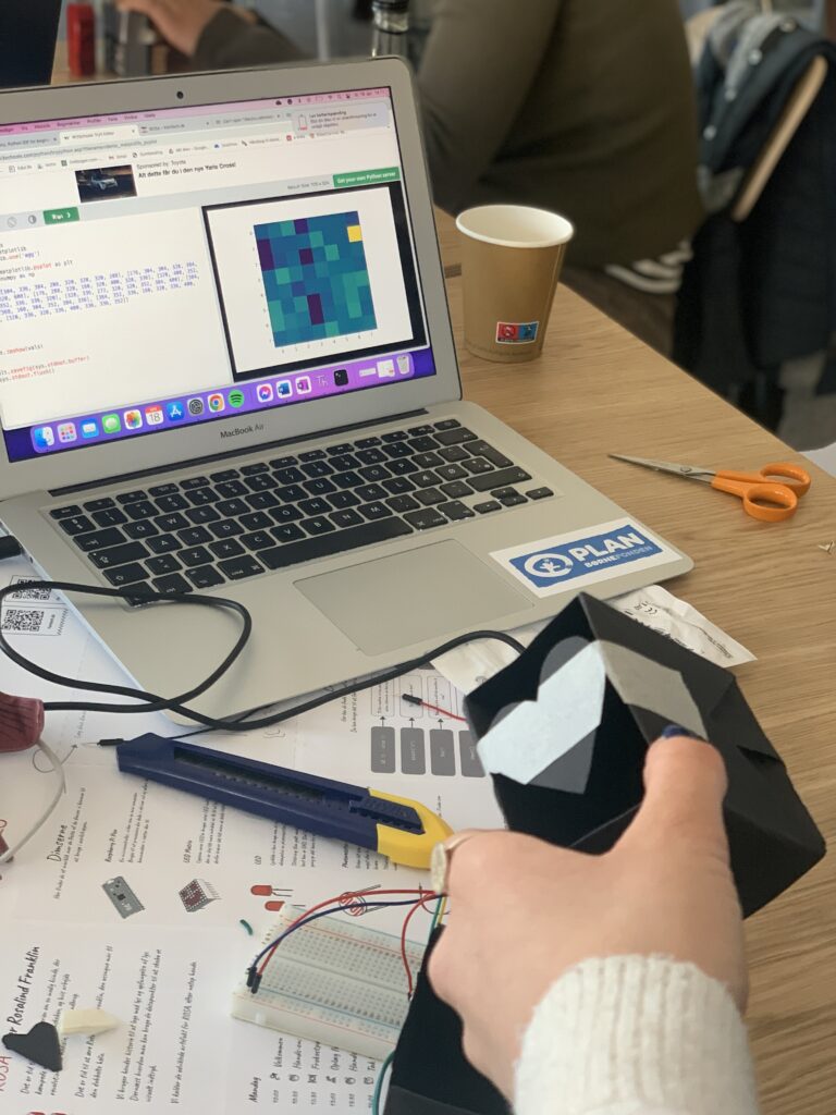
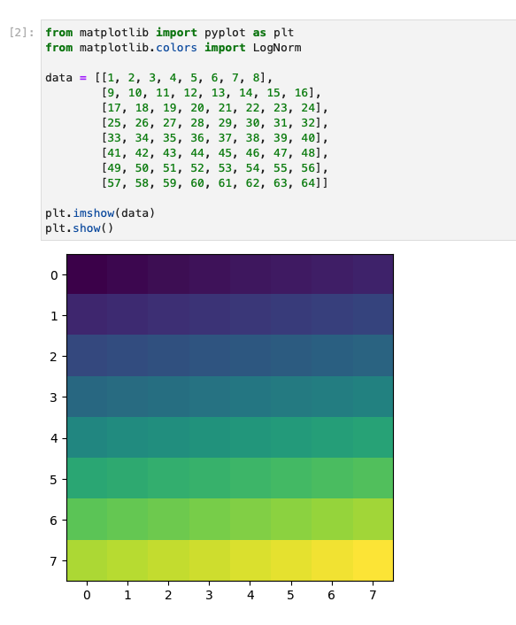
From this code you will get a string of 64 datapoints. Use those datapoints in Jupiter notebook: https://jupyter.org/try-jupyter/retro/notebooks/?path=notebooks/Intro.ipynb
Pasting like this code, but replacing with your datapoints
from matplotlib import pyplot as plt

data = [[1, 2, 3, 4, 5, 6, 7, 8],
        [9, 10, 11, 12, 13, 14, 15, 16],
        [17, 18, 19, 20, 21, 22, 23, 24],
        [25, 26, 27, 28, 29, 30, 31, 32],
        [33, 34, 35, 36, 37, 38, 39, 40],
        [41, 42, 43, 44, 45, 46, 47, 48],
        [49, 50, 51, 52, 53, 54, 55, 56],
        [57, 58, 59, 60, 61, 62, 63, 64]]

plt.imshow(data)
plt.imshow(data, cmap = 'Greys', alpha = 0.8, interpolation = 'bilinear')
plt.imshow(data, cmap = 'Greys', norm=LogNorm(), interpolation = 'bilinear')
plt.show()
And you will get a result like this:
Step 4 – The black box
For the next step in the project we want to gather all of the devices that we are working with in a box, that should work as a box for the camera. The box is working as a black room so the photoresistor is only detecting the light from the LED matrix, and not from anything else that could affect our results.
Final touches
This is a video showing how the black box camera that we made works.
It is important to note that the participants of the workshop was at very different levels, meaning that some of them got to iterate more times on the projects than others, and therefor there is not one definite answer to how the final project should look.
The most important is that the students got to be creative and work on the level suited for them. See pictures below to see what some of the participants came up with.