

FemTech DIKU event for excellent STX/HTX students – learning how to create Internet-of-Things Interactive Product – the IoT enabled Cyber Bear
“It is 6:00 early Monday morning in November. The alarm goes off, and Emma reaches out under her pillow and grabs her CyberBear and pushes its paw, the lights flashes green and Emma turns around and sleeps 100 min longer.”
CyberBear is an IoT interactive product, which connects to the scheduling system Lectio, which is used by Danish STX/HTX students. If the first class on the particular day for the particular student is cancelled, CyberBear will respond by flashing green lights – and the STX/HTX student can sleep 100 min longer. If the class is not cancelled is will flash red and the student need to get up.
http://femtech.dk/cyberbear/IMG_3480.MOV.mov
Below is a stepwise manual for how to create CyberBear (please feel free to re-use, but please remember referencing FemTech.dk). There is for sure things we did not consider, elements which can be done in different ways etc – any comments of how to improve the CyberBear design game is most welcome please email contact@femtech.dk
FemTech CyberBear instructions PDF
The PDF does not explain all, but together with the instruction of FemTech website, we hope it makes it possible for others to use it.
Follow the step by step guide to make your own:
Step 1
Installing Arduino IDE & Sparkfun Thing Dev Board ESP8266
1. Programming environment (we are using the Arduino Integrated Development Environment (IDE), which can be used for microcontroller programming, and this is where we are going to write the code)
1a) Download on this link Arduino IDE 1.8.2 https://www.arduino.cc/en/Main/Software and Install the Arduino IDE 1.8.2 on your computer (choose Mac or Windows Installer) (not the Arduino web editor)
1b) Only Mac – Unzip Arduino file and move to application folder. When you open Arduino it should open a sketch with empty Setup and Loop code.
2. Driver for the hardware (we are using a “Sparkfun Thing Dev Board ESP8266”, so we need to install drivers for the hardware board)
2a) open this link in new browser window: https://learn.sparkfun.com/tutorials/esp8266-thing-development-board-hookup-guide/setting-up-arduino
2b) go down to the heading: Installing the Add-on with the Arduino Board Manager and start here – you end BEFORE BLINK (then return to FemTech website)
- Open Arduino and install addon. Notice on Mac the “Additional Board Manager URLs” are located under Arduino>Preferences (not Files>Preferences) – but on PC it is Files>Preferences
- Install board manager, it should be in the bottom of Tools > Boards > Boards Manager. It’s named esp8266 – click install.
- Connect Sparkfun Thing Dev Board ESP8266 to Laptop via USB cable.
- Select “SparkFun ESP8266Thing Dev” board (NOTICE there are TWO ESP8266, you need the DEV one) in Tools>Boards
- Select usbserial port under Tools>Port
- Select Tools>Upload Speed>921600
If it does not work – and you are on Macyou need to update FTDI drivers: http://www.ftdichip.com/Drivers/VCP.htm. You need to update the driver with the Thing connected and in the ON power position. (The FTDI is a little chip on the Thing that converts between USB and Serial communication.
3. Install the LED strip and motion sensor libraries ()
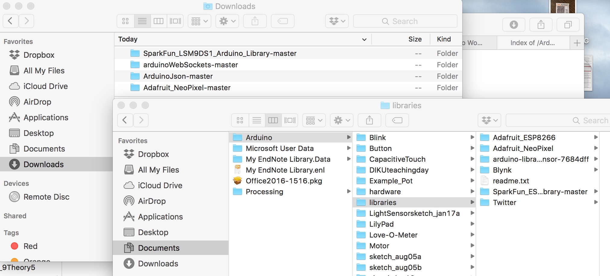
3a) Download the four library folders http://thesis.belhage.dk/ArduinoLibraries/
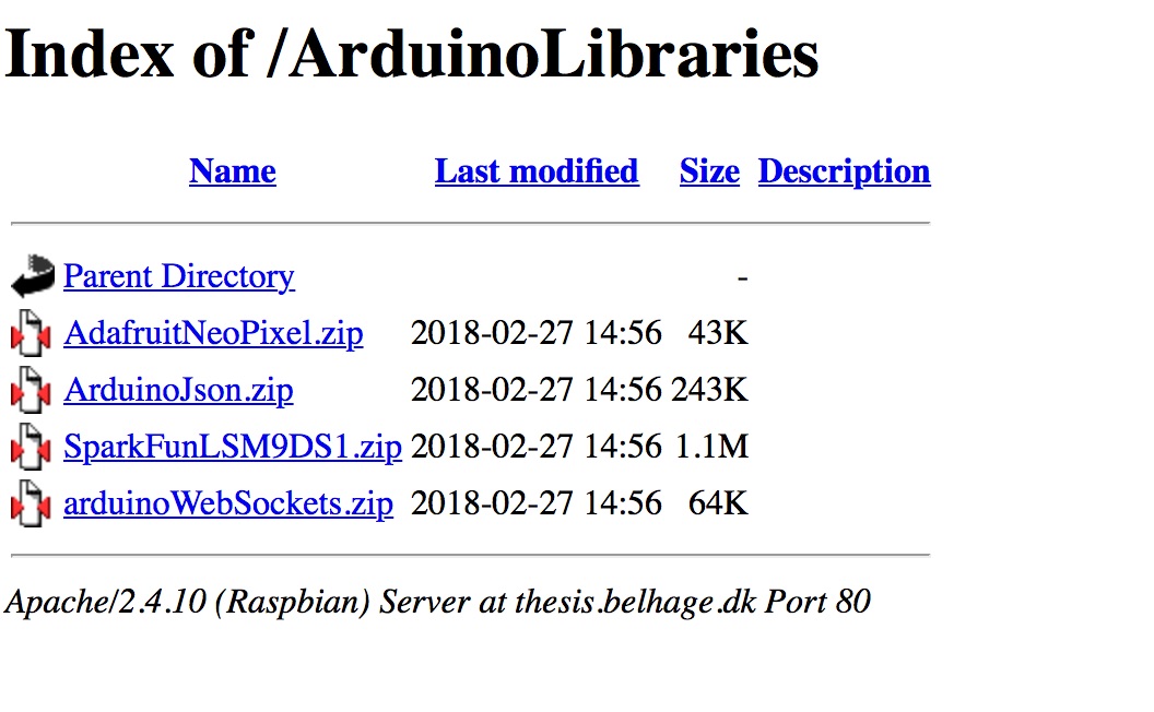
3b) Move the four folders from the download folder to Documents/Arduino/libraries
Step 2
Hello World – Make the thing blink
After installing the drivers, lets see if we are able to do the standard ‘ Hello world’, which in the world of the Thing means – lets get the Thing to Blink
- In Arduino IDE choose File>Examples>01.Basics>Blink. This should open a sketch with code.
- Save sketch in a folder on your Desktop, name the folder “FemTech” and the file Blink. On Mac to open up folder selection and creation in Finder, click the little downwards pointing arrow next to the name of the file.
- Make sure power switch is in ON position on the Thing and the USB is connected.
- Verify and Upload Blink to board. Verify is the little ‘check mark’ icon and upload is the icon with an arrow pointing to the right.
- See your Thing blink blue!
Step 3
Now we are going to make an external LED blink
First setup your Thing:
- Turn your Thing to “off”
- Removing the USB cable from your laptop
- Attaching your Thing to a ‘breadboard’ with elastic bands to hold it a little steady.
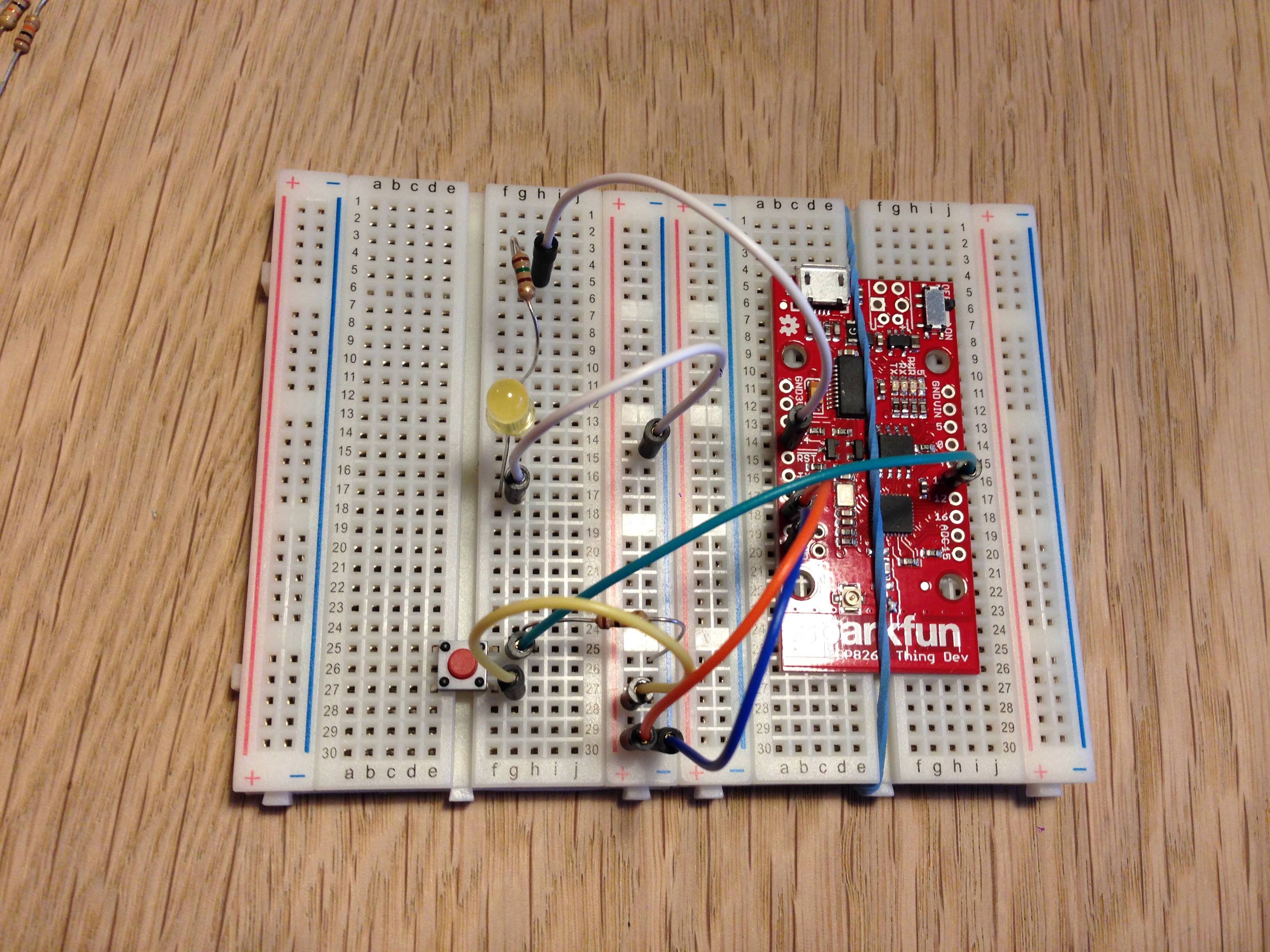
- Wire: Connect ‘5V’ to ‘+’ (red cable), ‘GND’ to ‘-’ (blue cable)
- Wire: ‘Pin14’ to ‘h5’
- Resistor (150 OHM, green and brown): ‘g5’ to ‘g11’
- LED: long leg ‘f11’, short leg ‘f17’
- Wire: ‘g17’ to ‘-’
Look at the picture above to see if you have wired it correctly
- Save your Blink as a new file calling it LEDblink.
- Above the function void setup() you need to add the following line: ‘const int ledPin = 14;’
- Now change everytime the code says ‘LED_BUILTIN’ with ‘ledPin’
- This change the LED blinking from the internal LED on the board called 5 to instead sending the same signal to 14. Which should be connected via a resistor to your LED.
- Re-connect usb
- Turn on power on Thing
- Verify LEDblink
- Upload LEDblink to the Thing
- See it blinking!!! Yahh
- Try to change how it blink
NOTICE: the Thing is not designed to be used on a breadboard, which means that if something does not work, try pushing the wires or the Thing a little – making sure that wires attached to the Thing is touching the sides of the pin hole.
A method is a function which can take parameters and do something
blinking_LED (X, Y, Z) – where X = LedPin; Y = delay time; Z = numbers of times to blink
Step 4
Adding a button to the circuit
Next step is that we want to control the Thing using a button, which mean that we want to control when the blinking starts
- Turn off Thing
- Remove USB from laptop
- Wiring up the Thing by adding to the existing setup: you need a Resistor(10k OHM, orange and brown), a button, and three extra wires
- Resistor goes from ‘-’ to ‘h25’ (to the right of the button)
- Button is placed so that it cross the board between ‘f25′-f27’ and ‘e25’-‘e27’
- Signal wire (green) goes from button right to Pin13 in Thing – ‘g25’-pin 13
- Button right leg is connected to ‘+’ (‘g27’-‘+’)
- In Arduino IDE open File>Examples>02.Digital>Button sketch
- Save As … in your Desktop FemTech folder as Button.
- Change “cont int buttonPin = 2;” to “cont int buttonPin = 13;“
- Change “cont int ledPin = 13;” to “cont int ledPin = 14;“
- Reconnect the USB to the computer
- Turn on the Thing
- Try to run the code and see what happens when pushing the button
void blinking_LED (const int output_led, int delay_nr, int total_blink){
  digitalWrite(output_led, LOW);
  for (int i = 0; i<total_blink; i++)
  {
    digitalWrite(output_led, HIGH);
    delay(delay_nr);
    digitalWrite(output_led, LOW);
    delay(delay_nr);
  }
}
Step 5
Getting the thing on the internet
Now we are going to get the Thing on the Internet using our existing hardware setup.
1) Opening a new Arduino Sketch and copy the below code into the sketch (click RAW in the right bottom window of the code (scroll down) for easy copy). Save it in your FemTech folder on your computer as “CyberBear”
2) Change the Internet and password settings in the code, by replacing the name of the network and password with the WIFI where you are
3) Check the signal Button pin is the right one accordantly to your wired board, if not make a change in your Hardware Board by moving the green wire to the right location (remember to TURN OFF the Thing before re-wiring)- like:
BUTTON_PIN = 14; //where your button signal is incoming
LED_PIN_RED = 16; // you do not have this on your hardware setup
LED_PIN_GREEN = 13; // linked to your LED on the breadboard
4) TURN ON the Thing, Try to compile and then upload the sketch to the Thing
5) Try to run the program and OPEN Serial Monitor to see whats happening (upper right corner of the Arduino sketch, ikon is a magnifying glass)
#include <ESP8266WiFi.h>

// WiFi network name and password:
const char * networkName = "NETWORK NAME"; //write the name of your WIFI network
const char * networkPswd = "mYpassWORD2"; //write the WIFI password

// Internet domain to request from:
const char * hostDomain = "femtech.dk"; //write the host domain name
const int hostPort = 80;

// Define which pins on your Thing for input (BUTTON_PIN) and output (LED_PIN)
const int BUTTON_PIN = 14;
const int LED_PIN_RED = 16; // red LEDs for pin 16
const int LED_PIN_GREEN = 13; // green LEDs for pin 13


void printLine()
{
  Serial.println();
  for (int i=0; i<30; i++)
    Serial.print("-");
  Serial.println();
}

void connectToWiFi(const char * ssid, const char * pwd)
{
  int ledState = 0;

  printLine();
  Serial.println("Connecting to WiFi network: " + String(ssid));

  WiFi.begin(ssid, pwd);
  while (WiFi.status() != WL_CONNECTED)
  {
    // Blink LED_BUILTIN while we're connecting: on the back side
    digitalWrite(LED_BUILTIN, ledState);
    ledState = (ledState + 1) % 2; // Flip ledState
    delay(200);
    Serial.print(".");
  }

  Serial.println();
  Serial.println("WiFi connected!");
  Serial.print("IP address: ");
  Serial.println(WiFi.localIP());
}

/* Return values:
 *  0 = success = yes //you can snooze; it is not raining; it is friday
 *  1 = failure = no //you need to get up; it is raining; it is not friday
 *  2 = connection failed
 *  3 = Timeout
 *  4 = bad reply
 */
int requestURL(const char * host, uint8_t port)
{
  printLine();
  Serial.println("Connecting to domain: " + String(host));

  // Use WiFiClient class to create TCP connections
  WiFiClient client;
  if (!client.connect(host, port))
  {
    Serial.println("connection failed");
    return 2;
  }
  Serial.println("Connected!");
  printLine();

  // This will send the request to the server
  /*
   * GET http://host/path/file.html HTTP/1.0
   * [headers here, if any]
   * [blank line here]
   * FemTech server:
   * http://femtech.dk/cyberbear
   * http://femtech.dk/cyberbear/cansnooze.php?gymId=[Id number of the gymnasium]&elevId=[Id number of the student]
   * http://femtech.dk/cyberbear/isnorain.php?cityName=[Name of the city where you want to know if there is no rain today or not]&country=DK
   * http://femtech.dk/cyberbear/isfriday.php
  */
  client.println("GET http://femtech.dk/cyberbear/isnorain.php?cityName=Copenhagen&country=DK HTTP/1.0");
  client.println();
  unsigned long timeout = millis();
  while (client.available() == 0)
  {
    if (millis() - timeout > 5000)
    {
      Serial.println(">>> Client Timeout !");
      client.stop();
      return 3;
    }
  }

  // Read all the lines of the reply from server and print them to Serial
  String line = "";
  while (client.available())
  {
    line = client.readStringUntil('\r');
    Serial.print(line);
  }
  Serial.println();
  Serial.println("closing connection");
  client.stop();
  if (line[1] == 'y')
    return 0;
  else if (line[1] == 'n')
    return 1;

  // bad reply
  return 4;
}

void blinking_LED (const int output_led, int delay_nr, int total_blink){
  digitalWrite(output_led, LOW);
  for (int i = 0; i<total_blink; i++)
  {
    digitalWrite(output_led, HIGH);
    delay(delay_nr);
    digitalWrite(output_led, LOW);
    delay(delay_nr);
  }
}

void resetInputPin (){
  pinMode(BUTTON_PIN, INPUT);
}

void setup()
{
  // Initilize hardware:
  Serial.begin(9600); //so we can see text in the serial monitor
  resetInputPin();
  pinMode(LED_PIN_RED, OUTPUT); //Red LED
  pinMode(LED_PIN_GREEN, OUTPUT); //Green LED
  pinMode(LED_BUILTIN, OUTPUT); //builtin LED helps to know what is going on, notice builtin led is connect to pin 5
  digitalWrite(LED_BUILTIN, LOW); // LED off
  digitalWrite(LED_PIN_RED, LOW); // LED off
  digitalWrite(LED_PIN_GREEN, LOW); // LED off
  // Connect to the WiFi network (see function below loop)
  connectToWiFi(networkName, networkPswd);
  Serial.print("Press button to connect to ");
  Serial.println(hostDomain);
}

void loop()
{
  blinking_LED (LED_BUILTIN, 1000, 1); //built in LED inform us if we are online
  if (digitalRead(BUTTON_PIN) == LOW)
  { // Check if button has been pressed 0
    Serial.println("waiting for you to release the botton");
    while (digitalRead(BUTTON_PIN) == LOW)
    {
      ; // Wait for button to be released
    digitalWrite(LED_PIN_RED, HIGH); // LED on to let you know that we are registring the pressure
    digitalWrite(LED_PIN_GREEN, HIGH); // LED on
    digitalWrite(LED_BUILTIN, HIGH); // Turn on LED
    }
    digitalWrite(LED_PIN_RED, LOW); // LED off
    digitalWrite(LED_PIN_GREEN, LOW); // LED off
    int response = requestURL(hostDomain, hostPort); // Connect to server
    Serial.println(response);
    if (response == 0)
    {
      //LED_PIN = output for blinking, for how long, and how many times, you can change the blinking patterns
      blinking_LED (LED_PIN_GREEN, 500, 5);
    } else if(response == 1)
    {
      blinking_LED (LED_PIN_RED, 500, 5);
    }
    digitalWrite(LED_BUILTIN, LOW); // Turn off LED
    delay(500);
    resetInputPin();
  }
}
Step 6
Who is Cyber Bear?
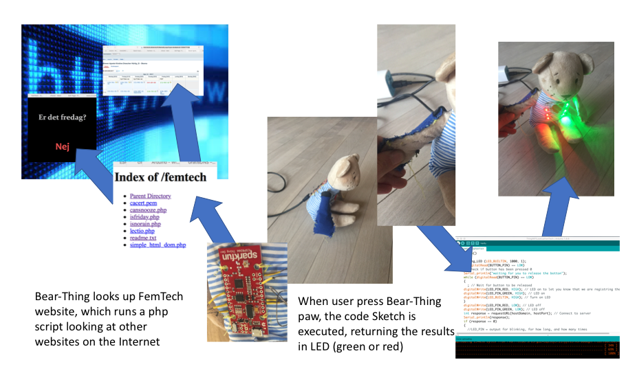
The FemTech CyberBear – is an ‘Internet-of-Things’ IKEA bear enabled by SparkFun Thing Dev Board ESP8266 to connect to the Internet, and when the user push a bottom, the CyberBear looks up a website and communicate the result via blinking LEDs (red or green).
Step 7
What kind of information can the FemTech Cyber Bear Look up?
The FemTech Bear-Thing is able to look up the FemTech website:
http://www.femtech.dk/
and then run one of the following three php scripts:
http://www.femtech.dk/cyberbear/isfriday.php
http://www.femtech.dk/cyberbear/isnorain.php
http://www.femtech.dk/cyberbear/cansnooze.php
It is important to notice that the websites alone does not respond to the question – it is only because we have the FemTech website, which runs the php script, which we have created and which parse the websites for the right answer.
Is it Friday?
The second script looks up the website http://erdetfredag.dk and returns the answer ‘yes’ or ‘no’.
Is it NOT raining?
The third script looks up the weather – default city is Copenhagen and answers ‘yes’ if the weather forecast says it is NOT raining, and ‘no’ if it is raining.
Can Snooze?
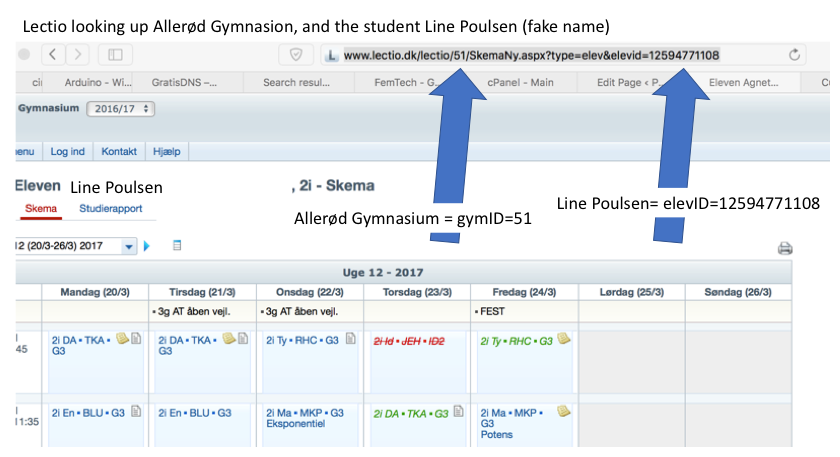
The first script links to Lectio of a given high school students at a given high school, looks up the time schedule for the current date, search through the content and identify whether the first classes that day have been cancelled. If they have been cancelled, the php script returns the answer ‘yes’, if the classes have not been cancelled it returns ‘no’. So basically, the first script answer the question ‘can I snooze?’
http://www.circonflexe.dk/femtech/cansnooze.php?gymId=[24]&elevID=[3432]
gymId=[Id number of the gymnasium]
elevId=[Id number of the student]
To find the Lectio ID of your school and of your own schedule, simply open a browser and logon to Lectio and look in the ‘addresse-bar’ in your brower – see example below:
Step 8
Creating the Textile Button
For the FemTech Textile button, we use amazing work by Paul Strohmeier, and adjust it for our use. The important part is that we need to construct a textile button, which fits to the bear’s right arm (seen from the back) and make pressure on the paw sent signals to the Thing, which then acts appropriately (as we coded earlier).
Also, it is important that the different wires (conductive threat) are not touching each other or getting crossed when we are sewn from the Thing to the textile bottom on the bear’s arm.
To do so you need to cut out the below template (in paper) and then use these to cut out appropriate pieces of fabric.
You need:
1) Ordinary fabric
2) Conductive fabric
3) Smart fabric
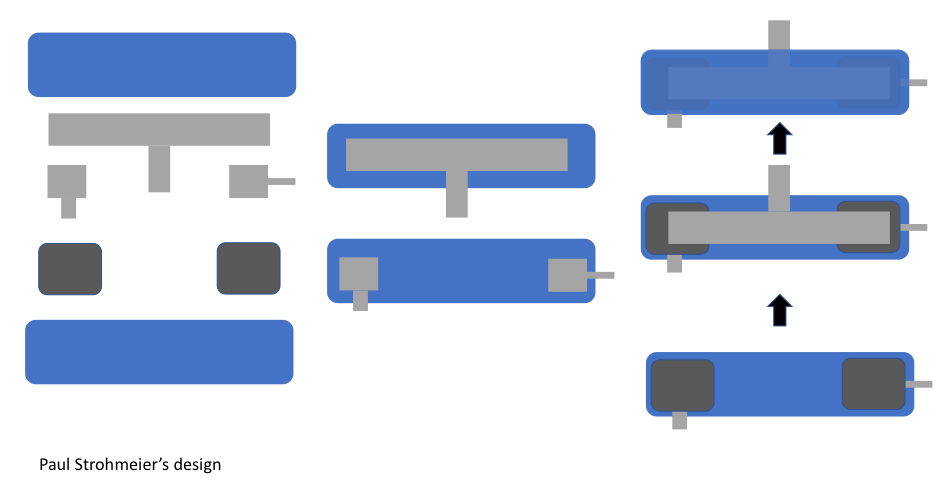
The Textile button is replacing our hardware from hard material to soft material.

Step 9
How should the textile button be attached to CyberBear?
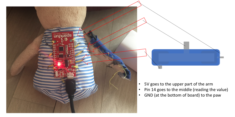
The textile bottom is designed to be placed in the right arm of the bear (seen from the back), when the Thing is attached on the back, with the USB cable going downwards.
This mean that on the right arm of the bear on the top, next to the head is a stick out, which will be connected to 5V on the board’s right side. The stick out at the paw should be connected to GND, and the one in the middle to pin 14.
However, first we will see if we can make it work on our current circuit using our current code – looking up whether it is friday today?
When the textile button works (it execute the programming code), then sew is on the Bear’s right arm with regular thread. When attached – test it again (using tape) for the breadboard setup.
Step 10
Wire up the Thing with conductive thread
Next step is to wire up the Thing with conductive thread instead of ‘normal’ wires – so we are detaching it from the breadboard.
We will place a long thread in each of the pins of the board, which we need to use – and we need conductive thread in pins 16, 13, and GND (on the left side of the board) and in pin 5V, 14, and GND (on the right side).
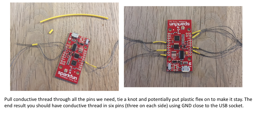
When all the thread is attached, then test whether the button still works, by attaching to the three button pins (5V, Pin14, and GND) using tape to make it easy – potentially taping it all to the table. PLEASE BE CAREFULL – THE THREADS MUST NOT TOUCH OR YOU RISK SHORT CIRCUITING!!
When you have tested that it works, we move on to attach the Thing to the Bear. Here we use ordinary thread and sew it on the back of the bear with the USB socket down (so the text ‘SparkFun’ in upside down)

Step 11
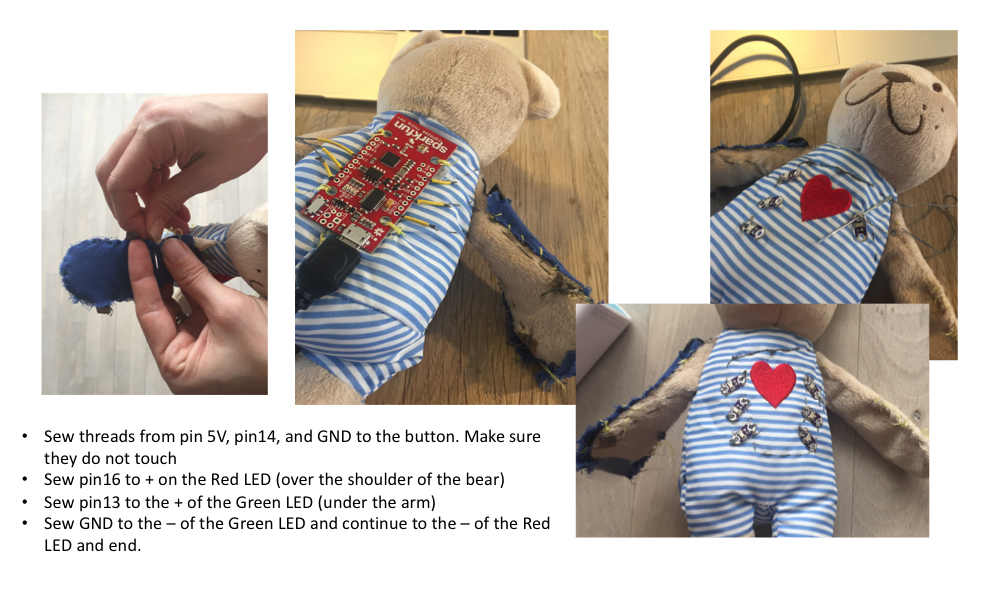
Sew on the LilyPad LEDs
Then sew on and attach all the conductive threads from the Thing to the button on the arm and on the different LEDs, which should be placed on the front of the bear.
Please notice the LEDs has both +/- – needs to be correctly attached and NOT TOUCHING each other.
Step 12
Cyber Bear Is done – Pimp it up?
Video of FemTech CyberBear in use – Now you should have a finish CyberBear – try to play around and make it look up your Lectio schedule, the weather, or whether it is friday?
Also potentially play around with the blinking patterns by changing the parameters in the code when you call the blinking method.
Finally, pimp you your CyberBear and give it a name.