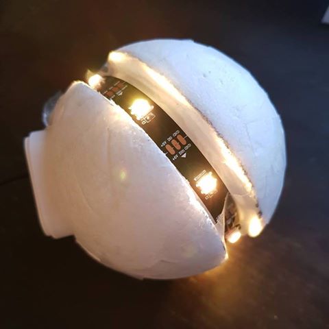
This week, FemTech.dk organised a two-day workshop with 26 students from eight different high schools in Copenhagen. During the workshop, each of the students created a “Cryptosphere”, which is an interactive device designed to make digital interaction effortful. The purpose is to make and preserve the importance of personal interaction in a time where it has never been easier to interact digitally. While creating their Cryptosphere, the students worked with microcontrollers, LED strips and motion sensors and reflected on the design of interactive devices. And all of them brought their Cryptospheres, microcontrollers, and sensors home!


- Physical IoT CryptoSphere interaction device for encrypting and decrypting scrambled messages. The CryptoSphere is an Internet-of-Things (IoT) device, which allows you to send and receive one-to-one and one-to-many encrypted messages across social media. The CryptoSphere has a special feature: messages are encrypted using physical movement.
- CryptoSphere Community of Facebook to send and receive one-to-one and one-to-many encrypted messages
- A web-application for writing and reading the messages
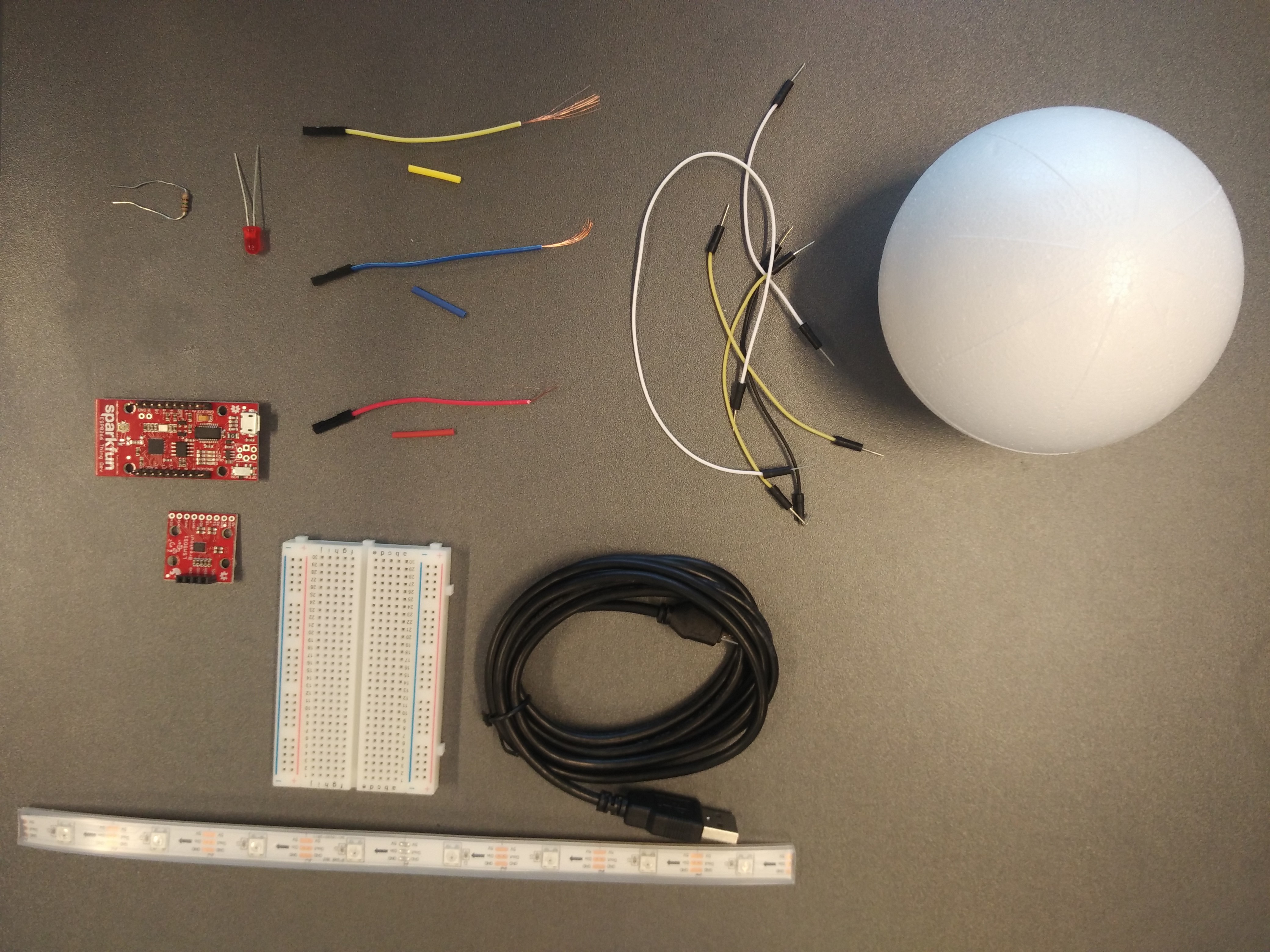
- A breadboard, one LED, one resistor, a few wires (to experiment making electronic circuits)
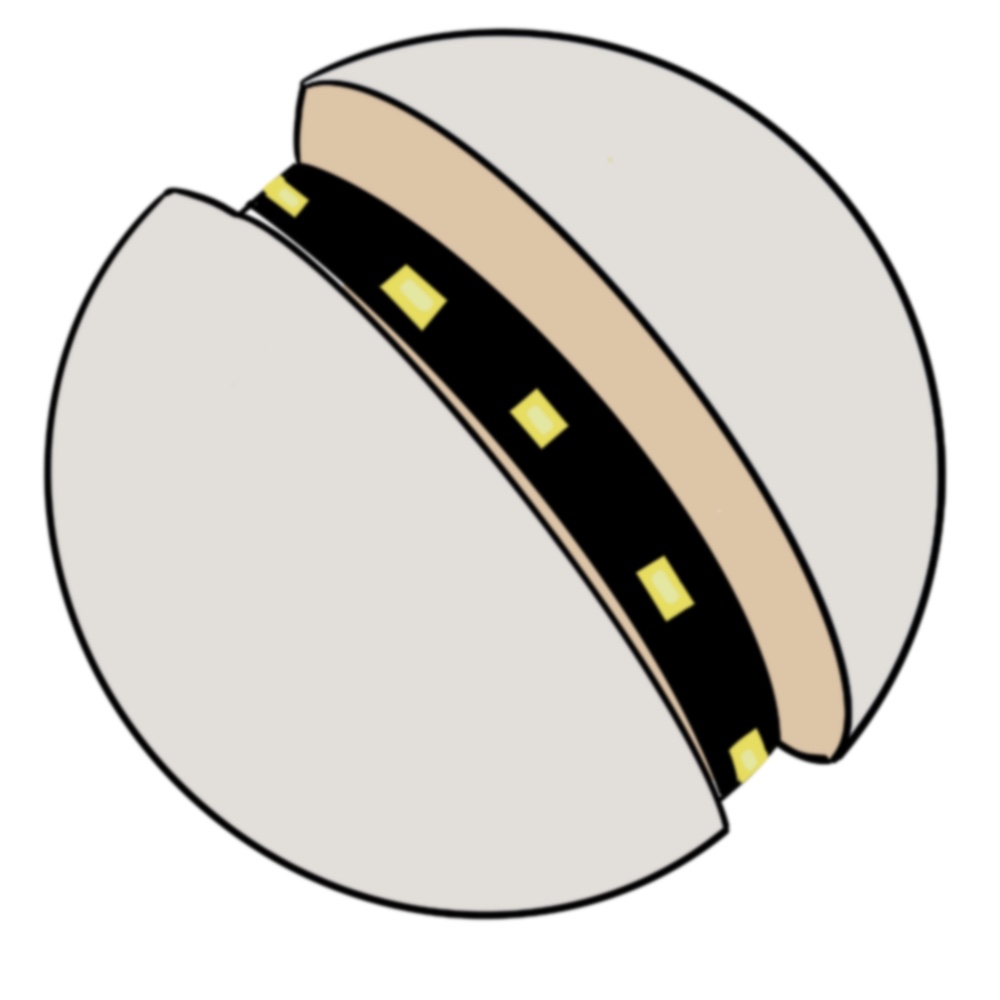
- A Flamingo sphere (10cm diameter)
- A LED Strip (8 LEDs) and three wires and skrumpe plast (in the picture, the yellow, blue and red)
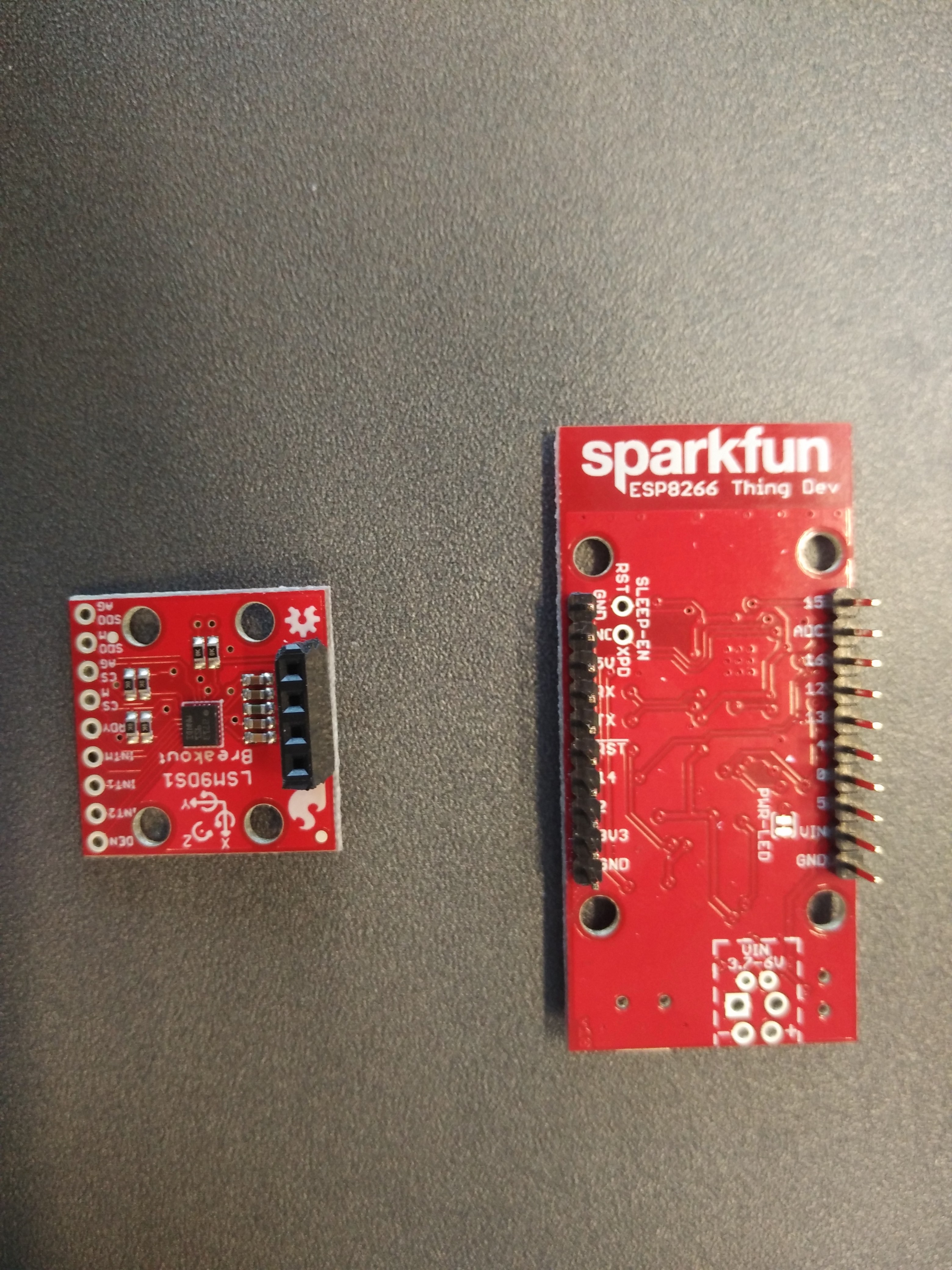
- One micro-controller (ESP8266 Thing)
- One motion sensor (LSM9DS1 sensor)
- One microUSB cable
- Facebook account
- Laptop/phone
Step 1
Installing Arduino IDE, Sparkfun Thing Dev Board ESP8266, & Library folders for Programming LEDstrips and Accelerometer:
Before we start, we need to install the Arduino IDE, different drivers and libraries on your computer. Below is a step-by-step instruction for Mac and PC for the installation. (PLEASE NOTICE that if you already have and installed Arduino IDE and the SparkFun ESP8266 driver – you might need to update these to make it work – EVERYBODY needs to do step 3)
You need to install:
1. Programming environment (we are using the Arduino Integrated Development Environment (IDE), which can be used for microcontroller programming, and this is where we are going to write the code)
1a) Download (also if you are updating your Arduino) on this link Arduino IDE 1.8.5 https://www.arduino.cc/en/Main/Software and Install the Arduino IDE 1.8.5 on your computer (choose Mac or Windows Installer) (not the Arduino web editor)
1b) Only Mac – Unzip Arduino file and move to the application folder. When you open Arduino it should open a sketch with empty Setup and Loop code.
2. Driver for the hardware (we are using a “Sparkfun Thing Dev Board ESP8266”, so we need to install drivers for the hardware board)
2a) open this link in new browser window: https://learn.sparkfun.com/tutorials/esp8266-thing-development-board-hookup-guide/setting-up-arduino
2b) go down to the heading: Installing the Add-on with the Arduino Board Manager and start here – you end BEFORE BLINK (then return to FemTech website)
- Open Arduino and install addon. Notice on Mac the “Additional Board Manager URLs” are located under Arduino>Preferences (not Files>Preferences) – but on PC it is Files>Preferences
- Install board manager, it should be in the bottom of Tools > Boards > Boards Manager. It’s named esp8266 – click install.
- Connect Sparkfun Thing Dev Board ESP8266 to Laptop via USB cable.
- Select “SparkFun ESP8266Thing Dev” board (NOTICE there are TWO ESP8266, you need the DEV one) in Tools>Boards
- Select usbserial port under Tools>Port
- Select Tools>Upload Speed>921600
If it does not work – you need to update FTDI drivers: http://www.ftdichip.com/Drivers/VCP.htm. You need to update the driver with the Thing connected and in the ON power position. (The FTDI is a little chip on the Thing that converts between USB and Serial communication).
3. Install the LED strip and motion sensor libraries
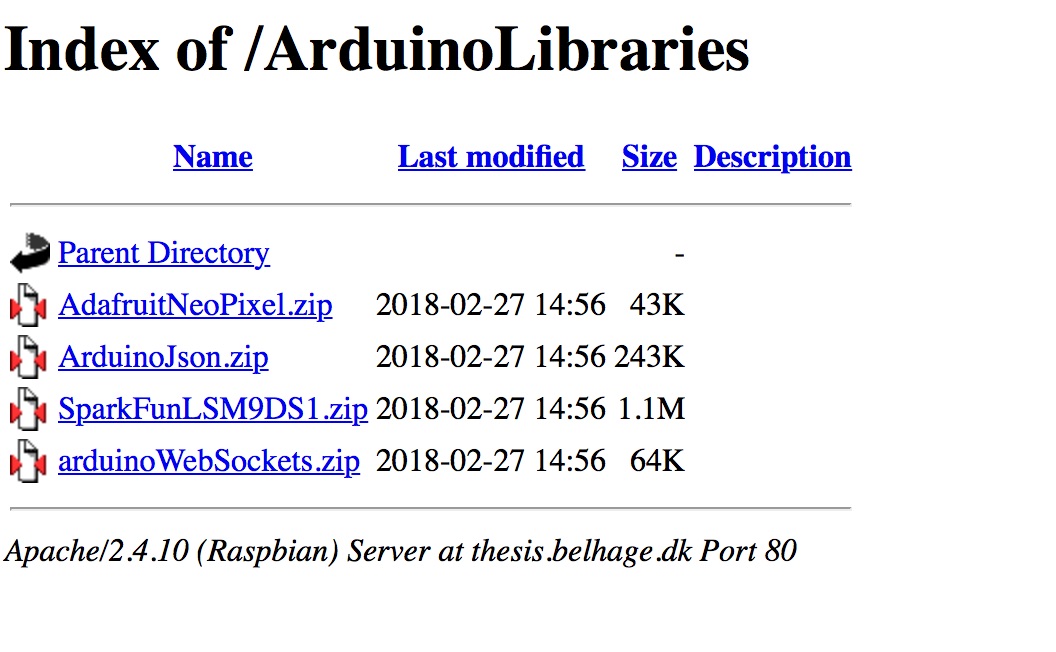
3a) Download four library folders for Programming LEDstrips and Accelerometer (motion sensor libraries).
First, you click on the link below and download the four .zip files: http://thesis.belhage.dk/ArduinoLibraries/
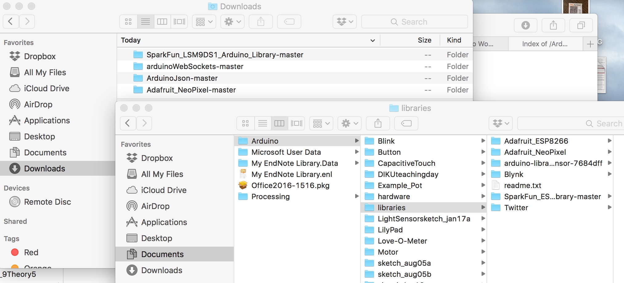
3b) When you have downloaded the folders. If the files are automatically unzipped, then simply move these from your download folder into to Documents/Arduino/libraries – else unzip the files and then move them.
Then, you download the code LEDstrip example. Forthat, you need to create a folder somewhere (maybe on the desktop) on your computer, called “FemTech.dk” and download these two files: exampleCode.zip and cryptoSphereCode.zip. Remember to unzip the files.
3c) Update your ESP8266 driver. This is only relevant if you had Arduino IDE installed on your computer previously. Then you need to update your board. You do this by going to Tool->select “Bord:” in the dropdown menu->select “Board manager” in the new dropdown menu (on the top).
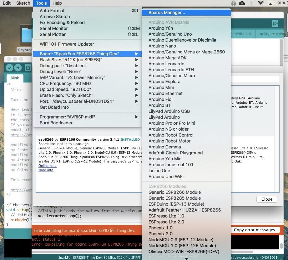
Then open the board manager and search “ESP8266” :
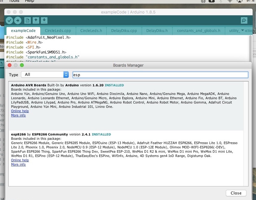
Then choose the esp8266 Community (by pressing it) and then click update:
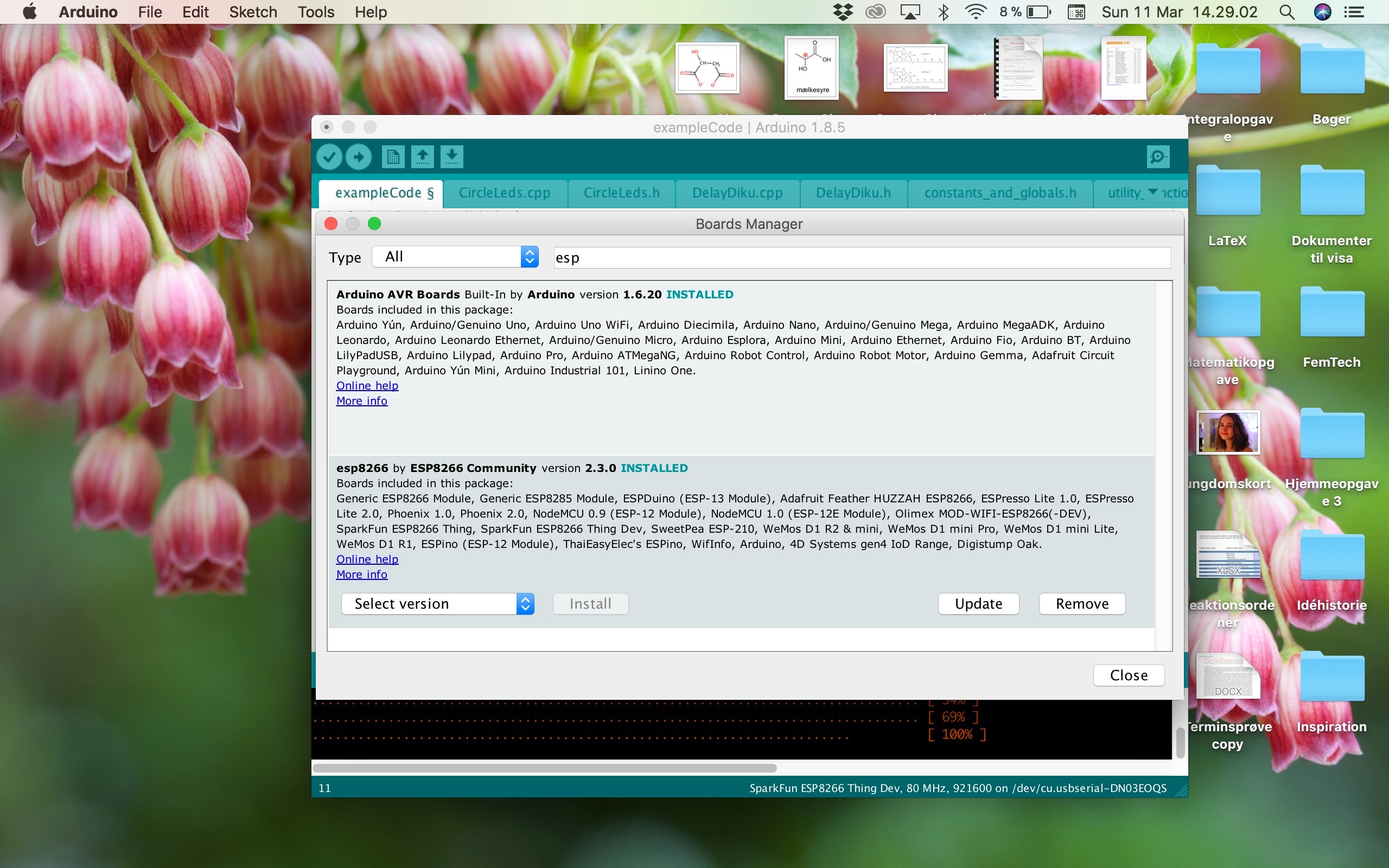
You have now successfully updated the board information.
Step 2
Hello World, Making the thing blink!
After installing the drivers, let’s see if we are able to do the standard ‘ Hello world’, which in the world of the Thing means: let’s get the Thing to Blink
- Plug and connect the Thing with the USB cable to your computer.
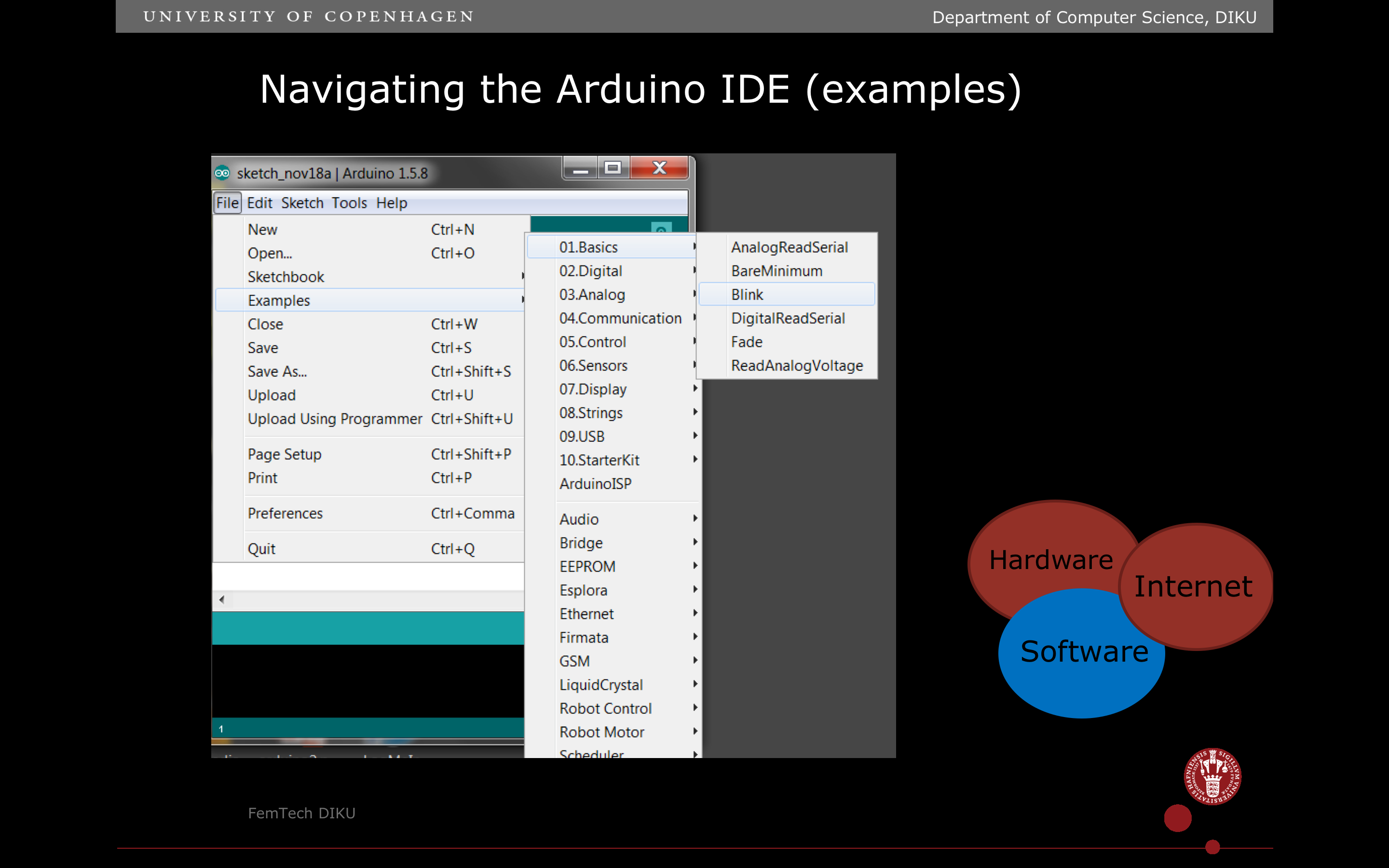
- In Arduino IDE choose File>Examples>01.Basics>Blink. This should open a sketch with code.
3. Save the sketch in a folder on your Desktop, name the folder “FemTech.dk” and the file Blink. On Mac to open up folder selection and creation in Finder, click the little downwards pointing arrow next to the name of the file.
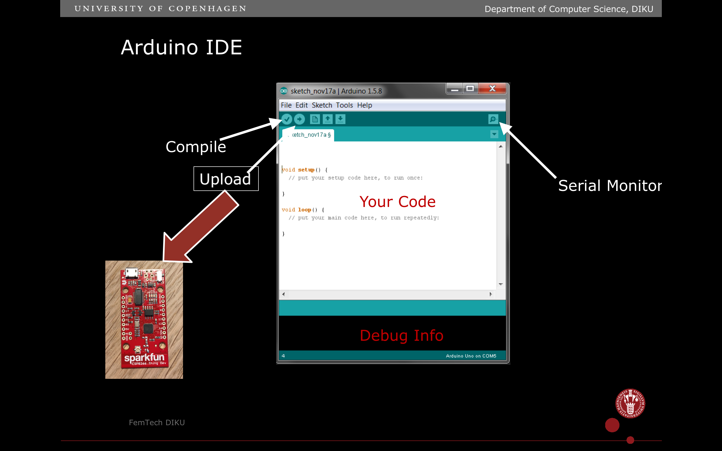
4. You navigate the Arduino user-interface – you need to know the below main part – Compile (translating the code into), Upload (uploading the code to the Thing), and then the Serial Monitor, where you can see text on the screen (useful for debugging).
5. Make sure power switch is in ON position on the Thing and the USB is connected.
6. Verify and Upload Blink to the Thing. Verify is the little ‘check mark’ icon and upload is the icon with an arrow pointing to the right.
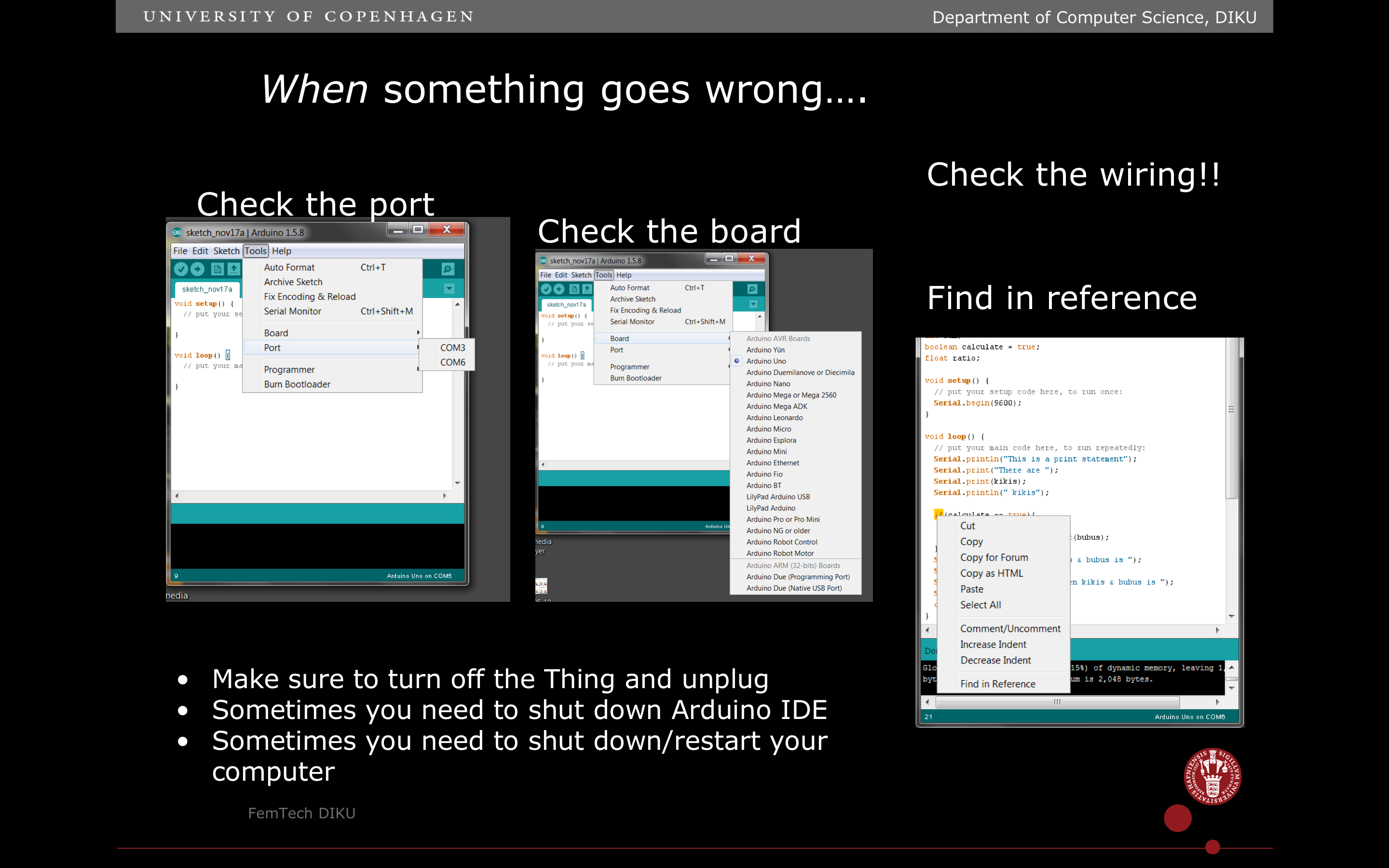
6a) PLEASE notice that you need to set the port right to make it work. To set the port: Choose Tools in the menu bar, Choose port in the dropdown menu, and then choose the Port, which starts with something like: “/dev/cu.usbserial” followed by capital letters and numbers – something like: “DN031D21”
7. See your Thing blink blue!
Now that we know how to make the internal LED work, the next step is to make the LED strip light:
Adding an LEDstrip to the microcontroller
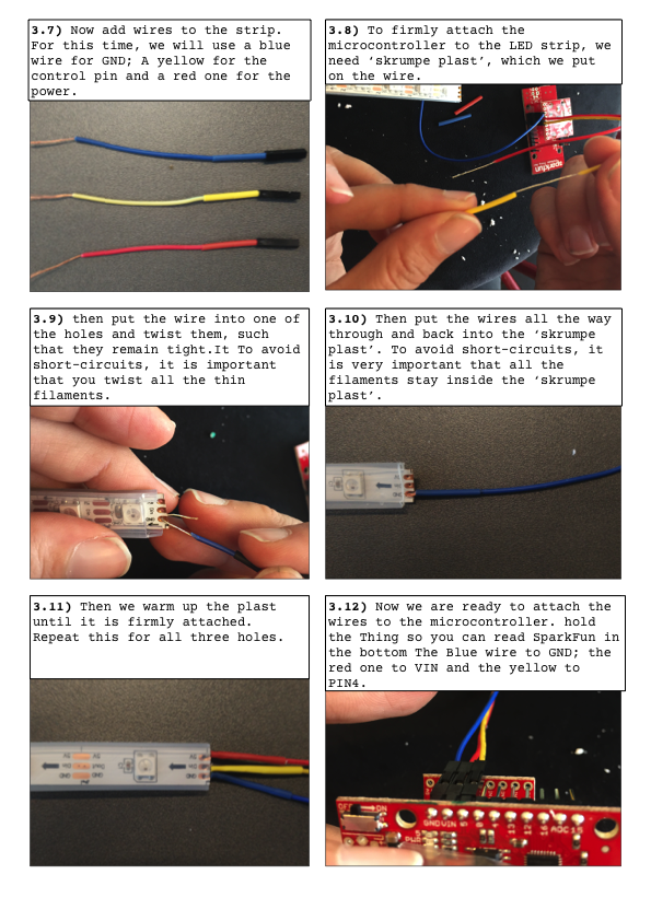
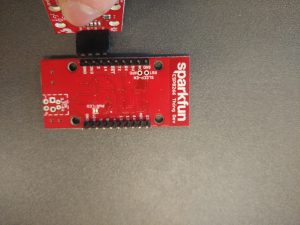
We want to add a LEDstrip to the microcontroller and play around with how it blinks. For that, we will first connect three wires between the LED Strip and the microcontroller. The images below guide you through each step.
Step 3
Adding an LEDstrip to the microcontroller
We want to add a LEDstrip to the microcontroller and play around with how it blinks. For that, we will first connect three wires between the LED Strip and the microcontroller. The images below guide you through each step.

Step 4
Experiment with the LEDStrip by changing the code
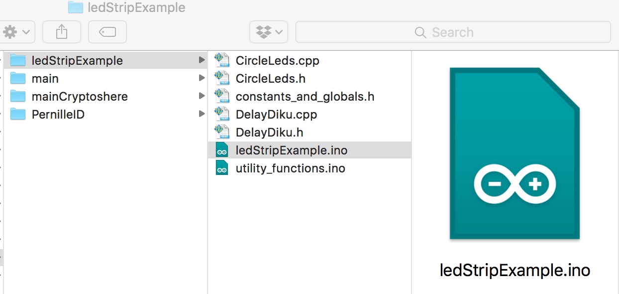
Now we will experiment with the LedStrip example code, created by FemTech.dk, and which you placed in your FemTech.dk folder on your desktop. (if you do not have it on your computer, you can go to the installation guide at the bottom to see how to download it step by step – or click this link: exampleCode.zip directly).
Find your FemTech.dk folder and open the sub-folder labelled: “exampleCode” – go into this folder and click the Arduino file exampleCode.ino
(Troubleshooting: If the exampleCode does not run, check if you have downloaded the pixel files and placed the files in the library folder – see step 01)
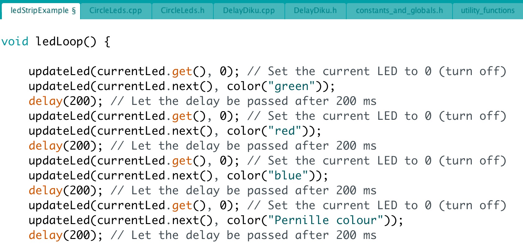
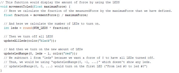
When you have the open file (exampleCode) and scroll down to the void ledLoop() and you should see the below code:
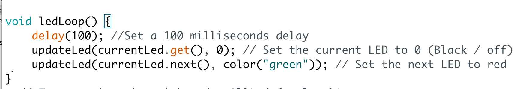
Try to compile and upload the code to your Thing and see what happens. What the above code says is to take the current LED, and turn it off, then move to the next, and turn it on with the color green, then wait 2 sec. This code runs in a loop.
Experiment: Make the lights a different color – try red or maybe blue?
Experiment: Make your own color pattern.
In your Arduino file, you can see different ‘tab’ in the top – called ‘CircleLeds.cpp’ or ‘utility_functions’ – if you click the ‘tab’ utility_functions’ and scroll down, you will see a function called int color(const char*name) – see below
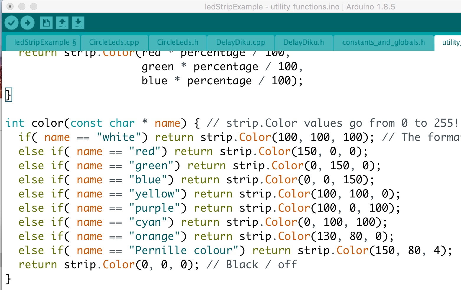
Try to change the code and make your own color – give it a name like ‘Pernille colour’ save and go back to the tab ‘LedExample’ and use your new color on your LED strip. Compile and upload the code and see what happens.
Experiment: Try to make a rainbow – the different LEDs blink in different colours – use below code for inspiration:
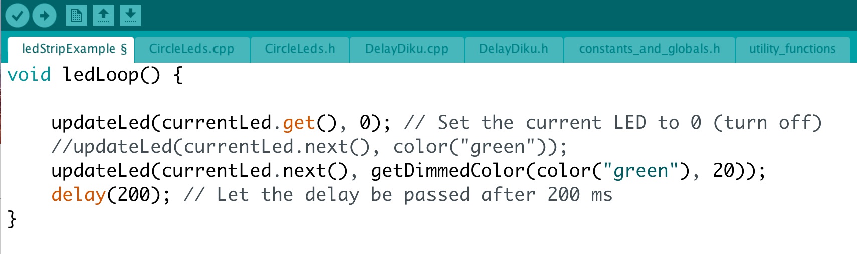
Experiment: Try to dim the brightness of the colors, use below code for inspiration:
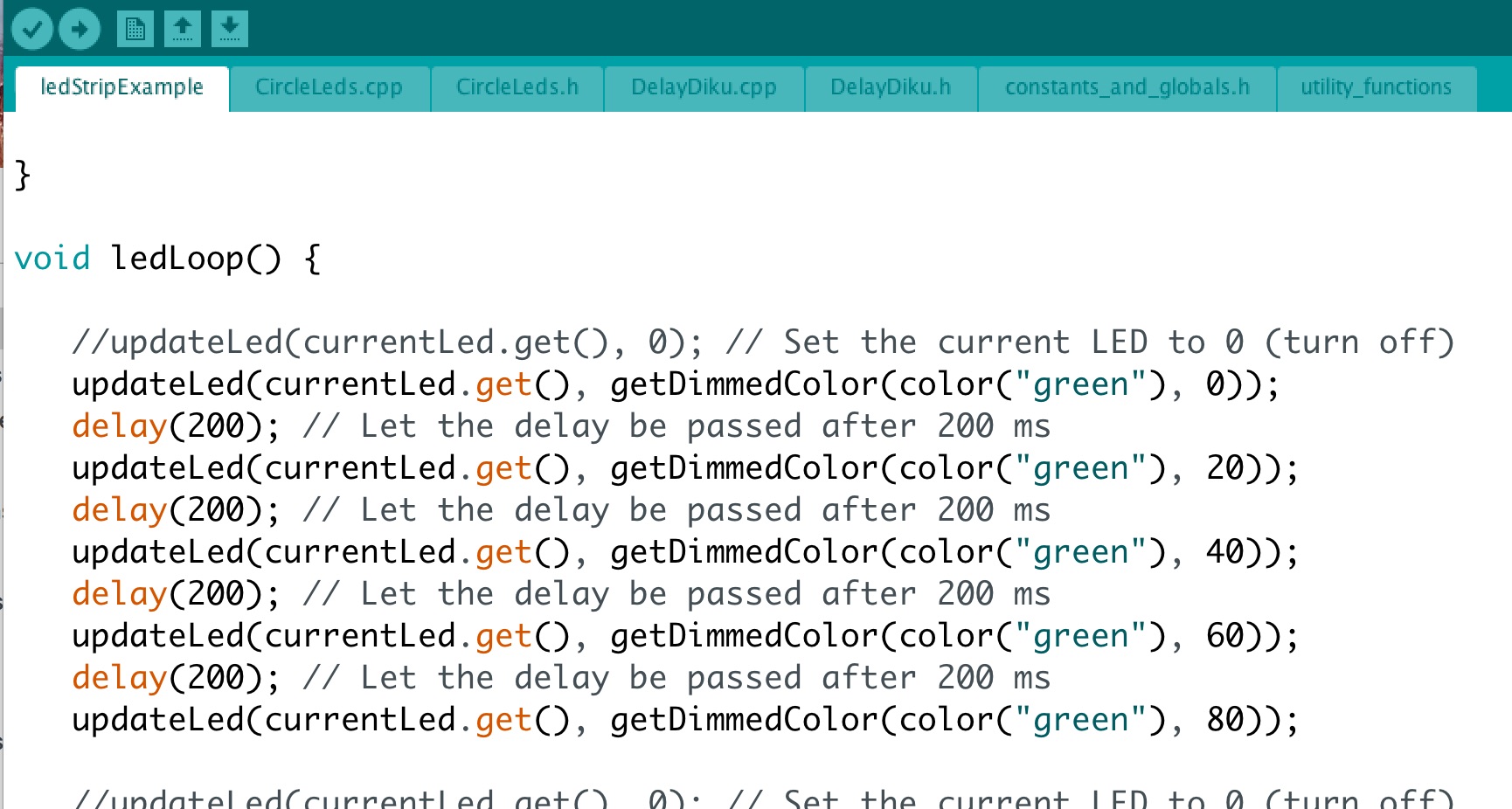
Experiment: Try to make only one specific LED blink (not the whole row) using a dimmed brightness – e.g. number 4 (remember we start counting from 0): Use the below code for inspiration – hint: Try to replace currentLed.get() with 4
Are there other things you would like to do with the LEDstrip? Maybe mixing the colors or the order by which the LED is blinking?
Step 5
Getting to know the motion sensor: Accelerometer and gyroscope
Interaction with digital technologies is not only about keyboards and touch screens. We can also use movement as an input device. When we are playing with micro-controllers, we are able to attach sensors which can detect movement, which we then can transform into signals for our devices. The sensor we are using for this workshop is called motion sensor (you can read more about it on Sparkfun website). This sensor has an accelerometer, a gyroscope and a compass.
In this workshop, we are going to play with the accelerometer and the gyroscope. The accelerometer is a sensor that can detect movement by tracking acceleration per unit of time around the x,y,z coordinates.
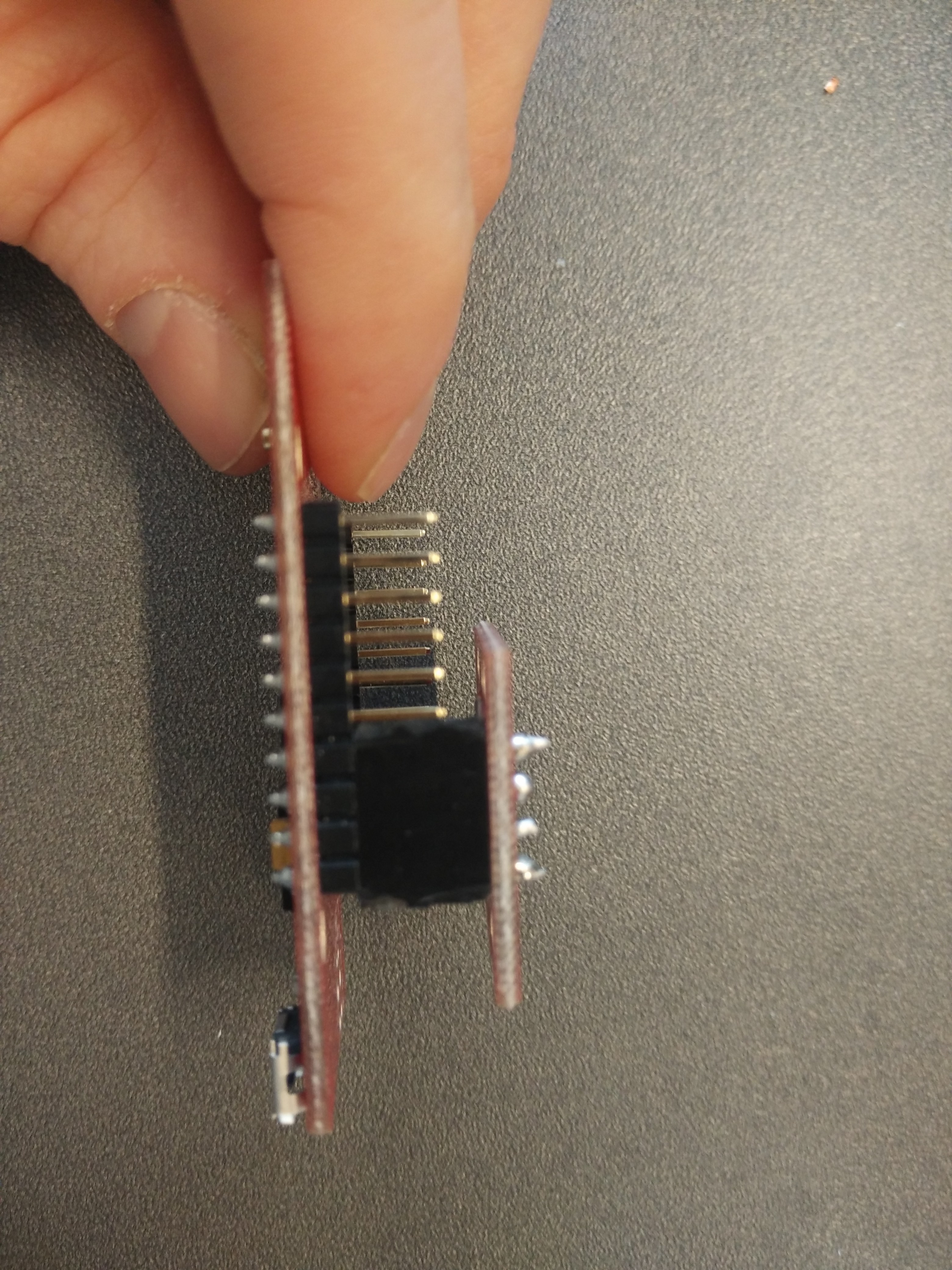
To add the motion sensor to the Thing – you need to make sure that the sensor is attached to the right pins:
Thing: GND=Sensor: GND
Thing: 3V3=Sensor: 1.9-3.6V
Thing: Pin 2=Sensor: SOA
Thing: Pin 14=Sensor: SCL
The following videos exemplify the movement around each of the x,y,z coordinates.
The gyroscope is a sensor that can detect movement by tracking the change of rotation around the x,y,z coordinates per unit of time.
Step 6
Experimenting with the accelerometer and gyroscope
First, add the motion sensor to the Thing:
To add the motion sensor to the Thing – you need to make sure that the sensor is attached to the right pins:
Thing: GND=Sensor: GND
Thing: 3V3=Sensor: 1.9-3.6V
Thing: Pin 2=Sensor: SOA
Thing: Pin 14=Sensor: SCL
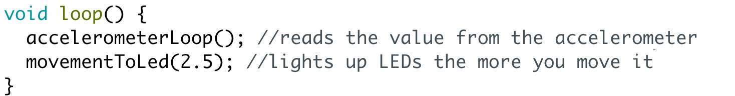
Then, experiment with the accelerometer and gyroscope using the code. For doing that, using the same example code as with the LED strip, you should uncomment some and uncomment other parts of the main “loop()” function; Like so:
Before:
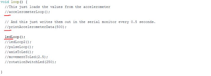
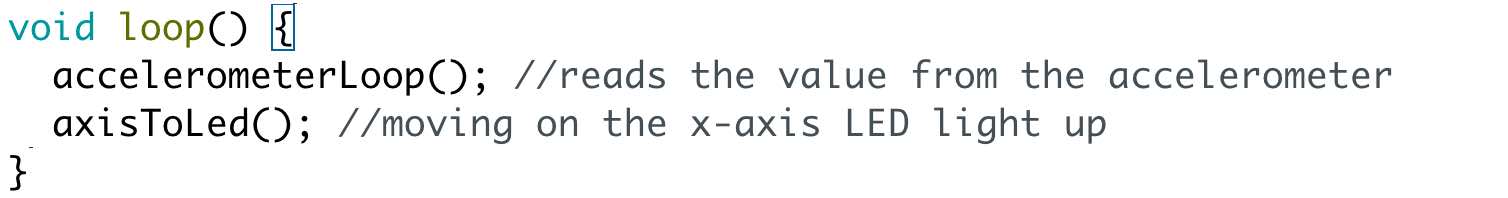
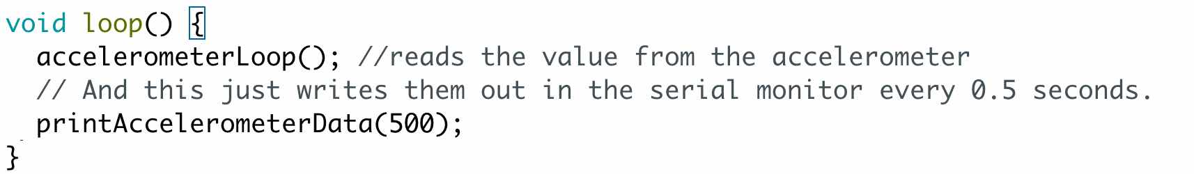
After:
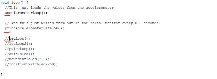
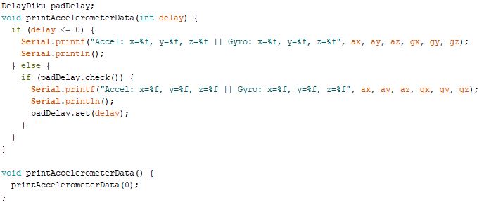
These two functions are fairly straightforward in their purpose; “accelerometerLoop” fetches the measurements from the accelerometer, and stores them in six variables: “ax”, “ay”, “az”, “gx”, “gy” or “gz”, which is the acceleration in the three dimensions and the rotation in the three dimensions respectively.
“printAccelerometerData()” writes out the data in the serial monitor so you can read it.
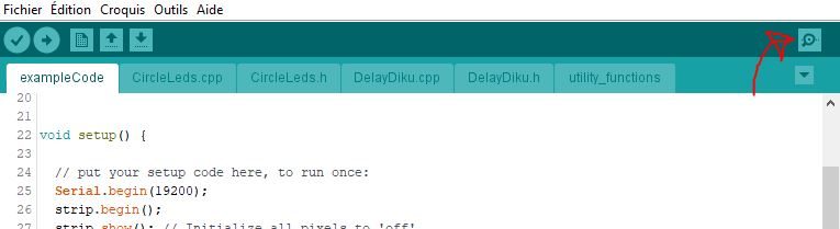
So, before compiling and uploading it to your device, open the serial monitor. The serial monitor is a window with all the text that your program “prints”. E.g. the code Serial.println(“Hello, World!”) would write a line with the text “Hello, World!” to the serial monitor.
You can open the serial monitor by clicking on the spyglass-button (top right).
Now you are ready to compile and upload!
Upon running the code, you should see some text appearing on the serial monitor. This is the data we get from the accelerometer. Specifically, the numbers written corresponds to the amount of movement (Acceleration in m/s^2) and rotational force (degrees per second) in each of the three dimensions.
Try picking up the device and see what happens to the numbers! It may be difficult at first, but try getting an intuitive understanding of why the numbers change. Use the drawing on the axes on the back of the accelerometer for reference.
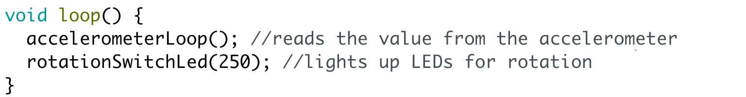
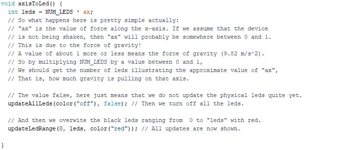
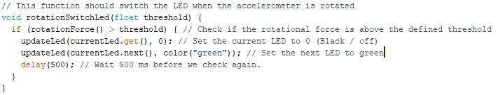
When you believe that you are ready to proceed, see what happens when you uncomment any of the functions “axisToLed”, “movementToLed”, or “rotationSwitchLed” (only one at a time – as demonstrated below).
Step 7
Now we will build the CryptoSphere. CryptoSphere is an IoT device, which is able to go online and help you encrypt and decrypt messages using movement. These are the steps you need to follow to create the Cryptosphere:


- Lets put CryptoSphere online
It is important that your CryptoSphere and your Phone are on the same local wifi, else they cannot connect and see each other. You need to be able to access your Facebook account from a browser (you need your password, if you normally use the Facebook app).
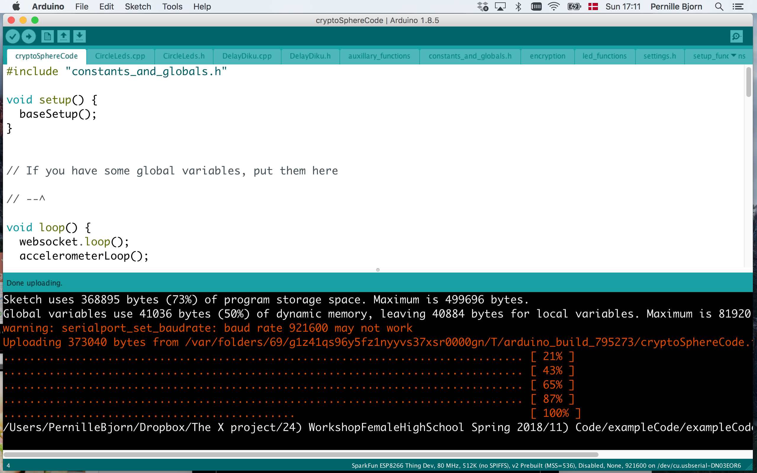
Now we will upload the code. First, you need to use the code you downloaded in step 01) – and which you placed in your FemTech.dk folder. Open the code cryptoSphereCode.ino – notice the different tabs in the top of the sketch code.
Now, you want to go to the “settings.h” in the IDE and find the variable “userId”. The value needs to be your Facebook-id specific to this project. You can find by going to this link and logging in to Facebook. You can do this both on your laptop or on your mobile device.
It will keep saying “connecting” in the blue button, but ignore that and look at the bottom of the page; There you will see your ID.
Copy paste this ID into the settings file at the “userId” variable.
While you are in the settings file, look at what options you have. For example, you could turn down (or up) the general brightness of the LEDs, change to a different WiFi (PLEASE notice that your CryptoSphere needs to be on the SAME wifi as your messaging device (laptop or mobile device) to function). When you get home, you need to change the wifi settings to your local network.
When you are ready, compile and upload the code. The web-app should now connect to your ball. If it doesn’t, try refreshing it.
If you are still having problems, ensure that the device on which you have the web-app is on the same network as your CryptoSphere.
Step 8
Encrypting and Decrypting Messages with CrytoSphere
The entire system consists of three parts:
1. The CryptoSphere
2. The web-app (http://thesis.belhage.dk/start.php)
3. A Facebook page (“CryptoSphere Community”)
Let’s look at a video showing how the CryptoSphere works:
The web-app comes in two colours; Blue and yellow for when you are sending and receiving a message respectively.
Sending a message
Following is the flow of sending a message:
1. Power on your CryptoSphere
2. Ensure that the CryptoSphere is on the same WiFi as your phone
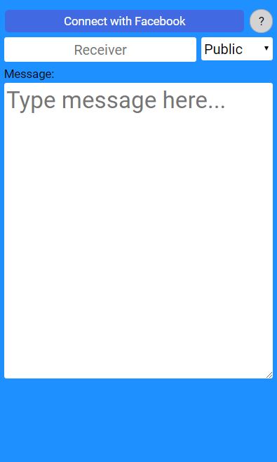
3. Navigate to the webapp (http://thesis.belhage.dk/start.php)
4. Click on “Connect with Facebook”
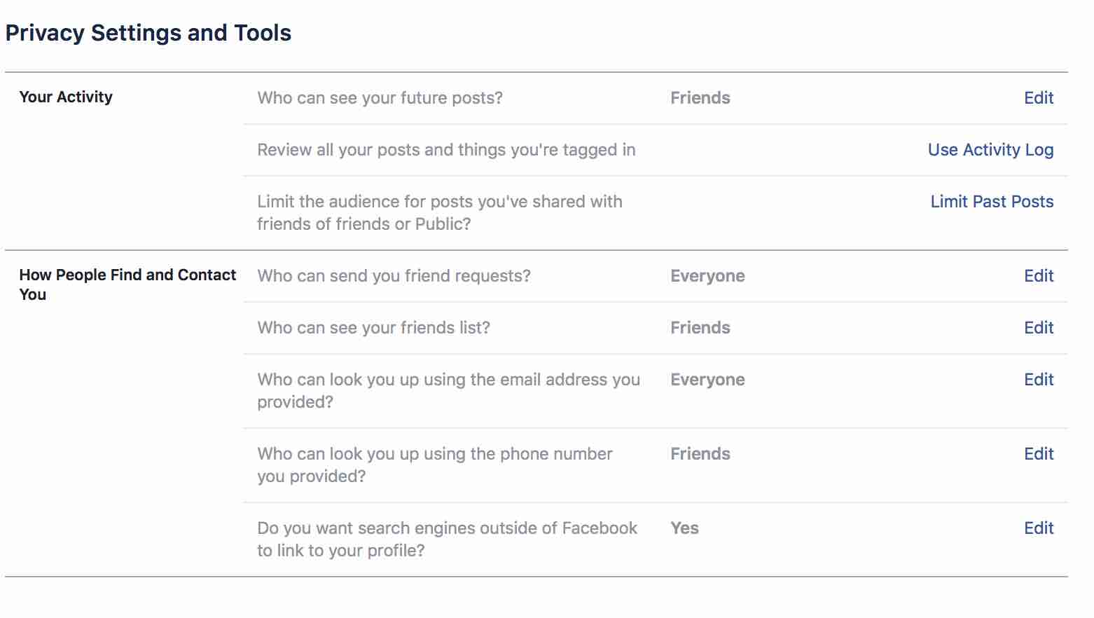
5. Write the name of the person you want to send to in “Receiver” *IF you cannot find Facebook contact name in the Web-App – it’s because of the receiver’s privacy settings. To solve this, the receiver needs to login to their Facebook profile under settings and set the “do you want search engines outside of Facebook to link to your profile?” to ‘YES’
6. Select Type Puzzle (everybody can decrypt if they solve the puzzle) or Secret (only 1 person with the code can decrypt)
7. Write the message in the large text area
8. Click “Send to CryptoSphere”
If you choose to encrypt your message using the “puzzle” option, then there will be one green LED and one (fainter) orange LED. The number of green LEDs indicates what level of encryption you are using. The result of a higher level of encryption is a more difficult puzzle for the receiver.
The goal now is to shake the CryptoSphere until the number of green LEDs is at the level you want to send.
Finally, you will twist the CryptoSphere in order to send the message.
If you choose to encrypt your message using the “secret” option, you need to have agreed on a combination of colors with the receiver. Then you need to select those colors on the CryptoSphere. This is done by carefully rotating the CryptoSphere in all three dimensions (This may take some practice).
Holding the CryptoSphere completely still until the LED goes out, will lock the color and continue to the next LED. To send the message to perform a long shake – until the LED lights disappear.
Also, since the webapp does support tagging people automatically (Yet!), you will need to tag them manually in the comments when you have sent the message:

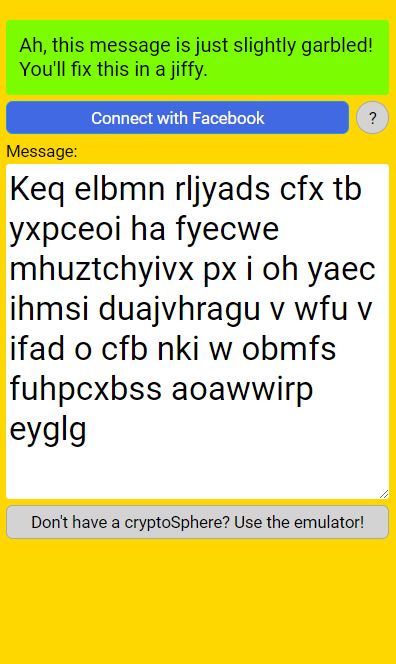
Receiving and reading a public message
A public message does not necessarily mean that it wasn’t meant for someone specifically; Just that anyone would be able to decode it (Either using their CryptoSphere or the emulator).
So you might receive a “public” message wherein you have been tagged, and thus it was likely meant for you.
When you see such a message you follow these steps:
1. Power on your CryptoSphere
2. Ensure that it is on the same WiFi as you laptop/mobile device
3. Click the link in the post (as seen above), which takes you to the yellow web-app.
3. Click “Connect with Facebook”
4. The puzzle should now be ready on your Cryptosphere
5. Solve the puzzle by turning all LEDs green
6. Submit the solution by doing a long shake with the CryptoSphere
7. And then you should see the decrypted message here!
For the puzzle, you need to turn all the LEDs green.
This is done by observing which LED is highlighted; The higlighted LED will be pulsing (Depending on how you animated it).
When doing a short shake you will flip the LED state. Remember that on higher levels of encryption, other LEDs may turn on or off, so observe what happens, and try to get them all to be green.
To switch to a different LED rotate your CryptoSphere clockwise (right) or anti-clockwise (left).
Once all LEDs are green you just do a long shake to submit the solution.
When you have submitted a correct solution, you will see the decrypted message in the webapp.
Receiving and reading a secret message
A secret message will still be posted to the facebook page, but unless you know the color combination, you will not be able to read it.
In order to read it, you still just click then link in the post, directing you to the yellow webapp. Connect to the CryptoSphere and start solving the puzzle.
The puzzle is the same as when sending a “secret” message. Thus using the CryptoSphere to select the same colors as the ones that were used to send the message. Once the correct colors are locked in place, perform a long shake to submit the solution, and then you should be able to read the decrypted message in the webapp.
Step 9
Reflecting upon the Open Design of CryptoSphere – join the CryptoSphere Community
- Physical appearance
- Tangible interaction
- Web-App Interface
- Social Media integration