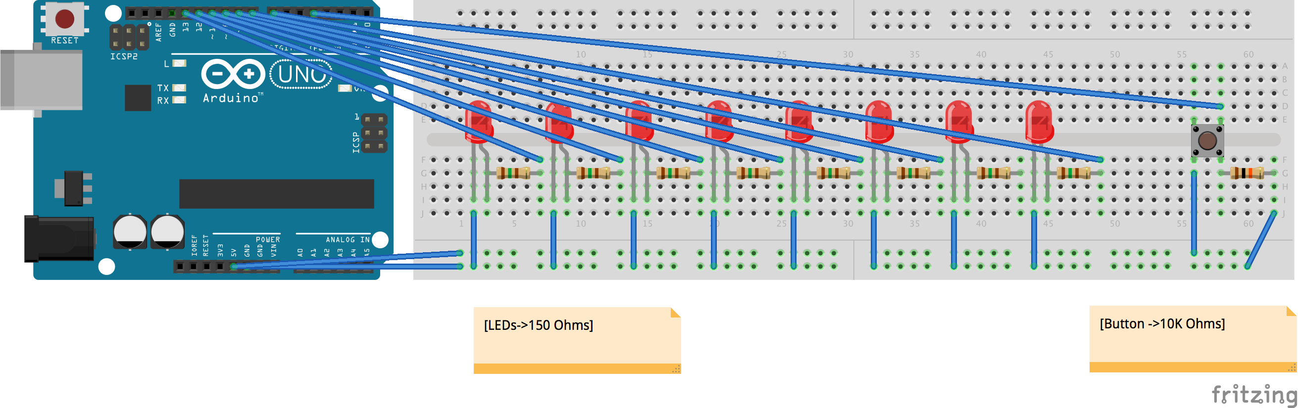
These schematics show how to connect your components (LEDs, button) and the resistors needed for each of them. These schematics show how to connect 8 LEDs because 8 is the size of the array being ordered in the code example, but you could certainly connect as many – and as little – LEDs as you wished. Given that you have enough Arduino pins left. Let’s go through the steps:
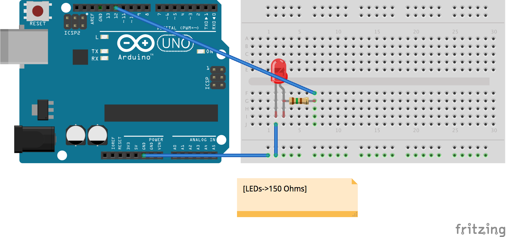
- Add one LED to the circuit. Notice that the LEDs have a polarity which, in this case, is indicated by having one lead longer than the other. The longer lead is the positive (also known as the anode) lead. This longer lead needs to be connected to a resistor, which is connected to one of the digital pins. The shorter lead should be connected to ground. An example of the code for the LED can be found in the Arduino app: File->Examples->01.Basics->Blink
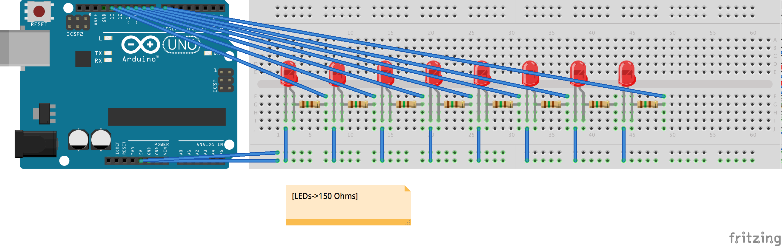
2. Repeat the same operation as in 1. As we want to independently control each LED, we will connect each of them to a different pin (so, if we want to have 8 LEDs, we will use 8 different pins).
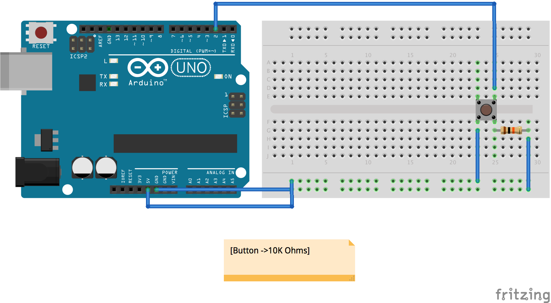
3. Now we are going to add a button, so we can interact with the algorithm. Follow the schematic to add a button to the circuit. An example of the code for the button can be found in the Arduino app: File->Examples->02.Digital->Button. In the following image, you can see how the complete circuit looks like.
4. This is how the complete circuit looks like. Now we can start coding how the circuit will behave. Go to the next section for detailed coding suggestions.